
A burr-free stamping die

A technology of burr-free stamping and stamping dies, which is applied in the direction of manufacturing tools, safety equipment, grinding drives, etc., and can solve problems such as inability to remove burrs, affecting the use of components, and damage to stamping support blocks

Active Publication Date: 2021-07-27
SHANDONG SHENLI RIGGING
View PDF7 Cites 1 Cited by
  • Summary
  • Abstract
  • Description
  • Claims
  • Application Information

AI Technical Summary

Problems solved by technology

The traditional burr stamping die cannot effectively remove the burrs generated by the pressed parts and parts, which will affect the use of the parts. If the power machinery of the stamping die fails, it may cause damage to the stamping support block

Method used


Image

  • A burr-free stamping die
  • A burr-free stamping die
  • A burr-free stamping die

Examples


Embodiment 1

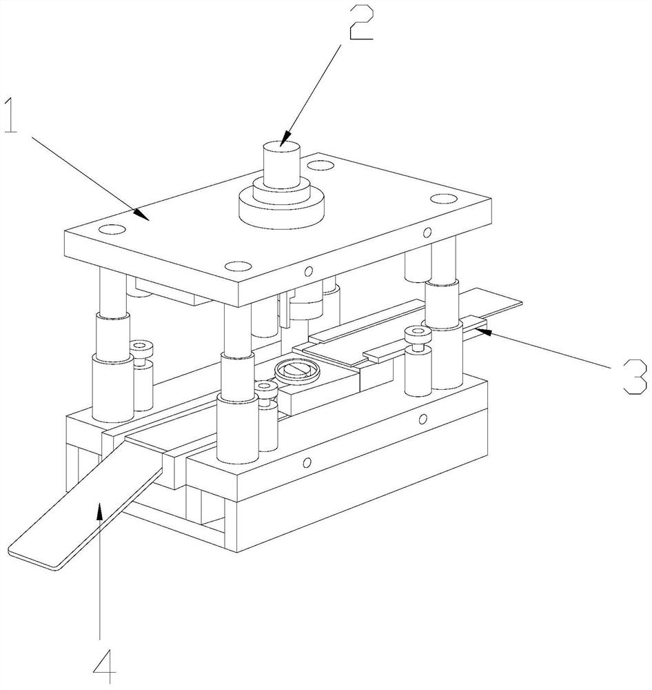
[0031] see Figure 1-Figure 5 , the present invention provides a burr-free stamping die, the structure of which includes a stamping die 1, a power pressing rod 2, a feeding device 3, and a discharge plate 4, and a power pressing rod 2 is provided at the middle position of the top of the stamping die 1, so that The stamping die 1 is mechanically connected with the power pressure rod 2, the feeding device 3 is installed on the bottom end of the inner side of the stamping die 1, and the left end of the stamping die 1 is provided with a discharge plate 4, and the stamping die 1 It is movably connected with the unloading plate 4;

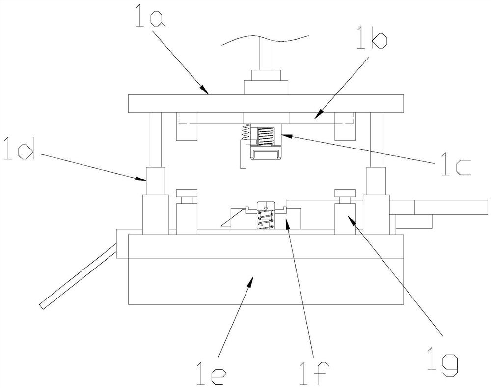
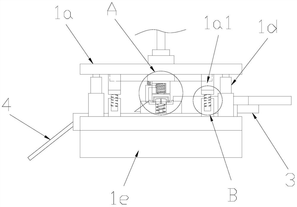
[0032] The stamping die 1 is composed of an upper die base 1a, an upper backing plate 1b, a stamping mechanism 1c, a guide post sleeve rod 1d, a lower die base 1e, a discharge mechanism 1f, and a buffer support mechanism 1g. The upper die base 1a The bottom end is provided with an upper backing plate 1b, the upper die base 1a is connected with the upper...

Embodiment 2

[0043] see Figure 1-Figure 6 , the present invention provides a burr-free stamping die, the buffer support mechanism 1g is composed of a limit cylinder seat 1g1, a thread groove 1g2, a buffer thread rod 1g3, and a buffer gasket 1g4, and the inside of the limit cylinder seat 1g1 is There is a thread groove 1g2, the thread groove 1g2 is provided with a buffer thread rod 1g3, the thread groove 1g2 and the buffer thread rod 1g3 are threadedly connected, and the top of the buffer thread rod 1g3 is provided with a buffer gasket 1g4, so The above-mentioned buffer threaded rod 1g3 is glued to the buffer gasket 1g4.

[0044] The upper mold base 1a and the lower mold base 1e are parallel to each other, and the length and width are the same. The top clamping rod 1f21 and the stamping support block 1f5 are fitted together through the tapered extrusion groove 1f51. The buffer gasket 1g4 is made of rubber material, which is not suitable for damage and has strong flexibility. The feeding d...


PUM


Abstract

The invention discloses a burr-free stamping die, the structure of which comprises a stamping die, a power pressing rod, a feeding device, and a discharge plate. The raw materials are punched and formed, and the circular curved mold is driven by the power push rod to rotate and stamped, and the surface of the circular curved workpiece is polished through the grinding cap, so that the burrs on the surface of the circular curved workpiece can be polished clean to avoid affecting the use of parts. The stamping die is divided into two by the stamping support block on the unloading mechanism to clamp the circular curved workpiece to prevent the circular curved workpiece from being rotated by the grinding cap during grinding, which reduces the grinding efficiency. The stamping die uses the buffer support mechanism to The limitation of the downward movement distance of the upper mold base prevents damage to the stamping support block when the driving device fails.

Description

technical field [0001] The invention relates to the field of molds, in particular to a burr-free stamping mold. Background technique [0002] The existing method of processing and forming of circular curved workpieces is usually completed by the stamping process. The direct and primary factor affecting the height of the workpiece burrs after stamping is the gap between the upper and lower cutting edges, followed by the friction between the pressing material, the sides of the upper and lower cutting edges and the punching section , punching speed, mold use heat, vibration. The traditional burr stamping die cannot effectively remove the burrs generated by the pressed parts and parts, which will affect the use of the parts. If the power machinery of the stamping die fails, it may cause damage to the stamping support block. Contents of the invention [0003] Aiming at the deficiencies of the prior art, the present invention is realized through the following technical solution...

Claims


Application Information

Patent Timeline
Patent Type & Authority Patents(China)
IPC IPC(8): B21D28/02B21D28/04B21D28/14B21D28/16B21D28/20B21D55/00B24B9/04B24B41/06B24B47/12
CPCB21D28/02B21D28/04B21D28/14B21D28/16B21D28/20B21D55/00B24B9/04B24B41/06B24B47/12
Inventor 汤成
Owner SHANDONG SHENLI RIGGING
Learn More