

High-efficiency building concrete stirring machine
A technology for concrete and construction, applied in cement mixing devices, clay preparation devices, liquid ingredient supply devices, etc., can solve problems such as the inability to adjust the water supply, and achieve the effect of increasing the mixing effect
- Summary
- Abstract
- Description
- Claims
- Application Information
AI Technical Summary
Problems solved by technology
Method used
Image

Examples
specific Embodiment approach 1
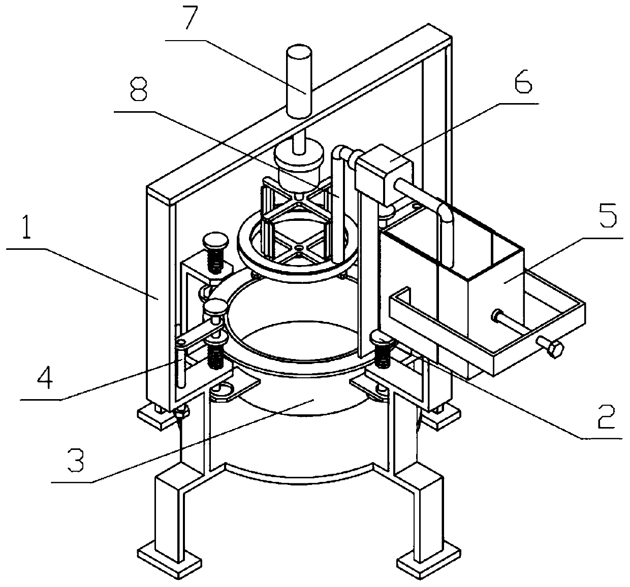
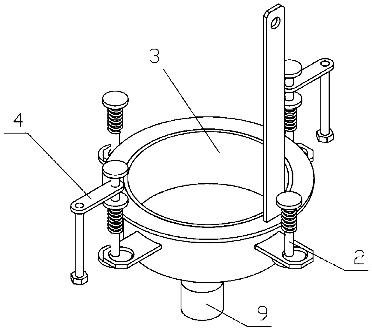
[0037] Combine below Figure 1-14Describe this embodiment, a high-efficiency construction concrete mixer, including device support 1, restricting mechanism I2, mixing box 3, restricting mechanism II4, water supply mechanism 5, water supply pipeline 6, stirring mechanism 7, connecting hose 8 and swing mechanism 9, The left and right sides of the device bracket 1 are slidingly connected with a limiting mechanism I2, and a compression spring I is fixedly connected between the limiting mechanism I2 and the device bracket 1, and the front and rear sides of the device bracket 1 are connected with a limiting mechanism II4. A compression spring II is fixedly connected between Ⅱ4 and the device bracket 1, the left and right sides of the stirring box 3 are respectively clearance-fitted on the two limiting mechanisms Ⅰ2, and the front and rear sides of the mixing box 3 are respectively clearance-fitting on the two limiting mechanisms Ⅱ4, A water supply mechanism 5 is fixedly connected to...
specific Embodiment approach 2
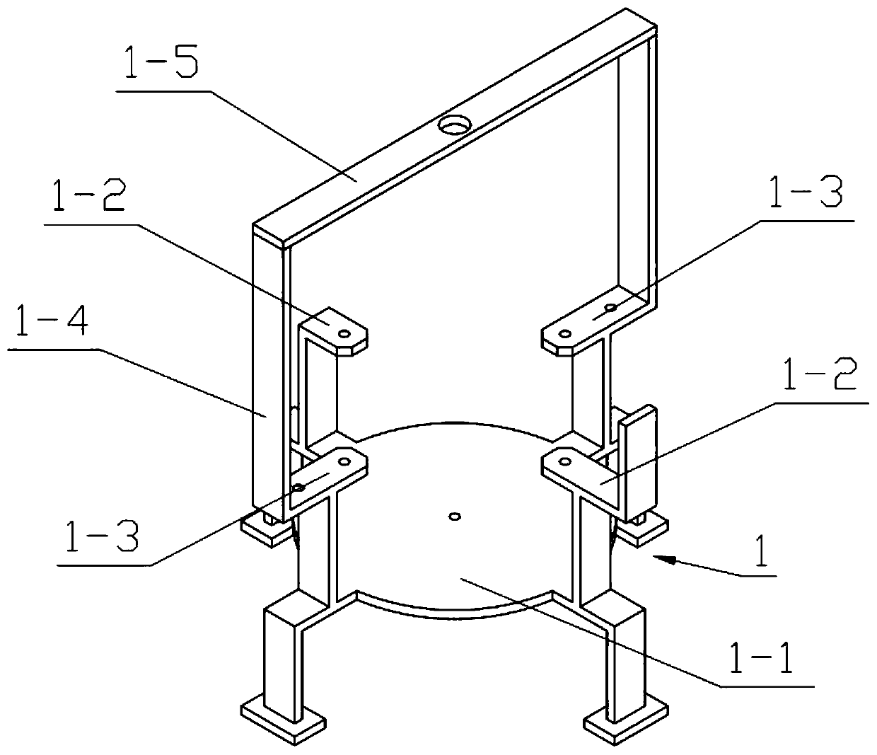
[0039] Combine below Figure 1-14 Describe this embodiment, this embodiment will further explain the first embodiment, the device bracket 1 includes a bottom plate 1-1, a support frame I1-2, a support frame II1-3, a support plate I1-4 and a connecting plate 1-5, The left and right sides of the bottom plate 1-1 are fixedly connected with the support frame I1-2, the front and rear sides of the bottom plate 1-1 are fixedly connected with the support frame II1-3, and the upper ends of the two support frames II1-3 are fixedly connected with a support Plate I1-4, a support plate I1-4 is fixedly connected between the upper ends of the two support plates I1-4.
specific Embodiment approach 3
[0041] Combine below Figure 1-14 Describe this embodiment, this embodiment will further explain the second embodiment, the restriction mechanism I2 includes the gap column I2-1, the spring baffle I2-2 and the support plate I2-3, the upper and lower ends of the gap column I2-1 The spring baffle Ⅰ2-2 and the support plate Ⅰ2-3 are respectively fixedly connected, and the two support frames Ⅰ1-2 are slidably connected with the gap column Ⅰ2-1, and the spring baffle Ⅰ2-2 and the support frame Ⅰ1-2 are fixed Connected with compression spring I.
PUM
 Abstract
Description
Claims
Application Information