Rainwater flow dividing equipment for urban drainage system

A technology for urban drainage and diversion equipment, which is applied in waterway systems, sewer pipe systems, and sewage removal. It can solve problems such as troublesome and time-consuming, and achieve the effect of avoiding wear and saving time.

Active Publication Date: 2020-06-19
广西乾坤环保科技有限公司
View PDF6 Cites 0 Cited by
  • Summary
  • Abstract
  • Description
  • Claims
  • Application Information

AI Technical Summary

Problems solved by technology

[0005] The purpose of the present invention is: in order to overcome the shortcomings that people need to disassemble the pipeline first to clean up the garbage in the valve, which is very troublesome and time-consuming. Time-Saving Stormwater Diversion Devices for Urban Drainage Systems

Method used


Image

  • Rainwater flow dividing equipment for urban drainage system
  • Rainwater flow dividing equipment for urban drainage system
  • Rainwater flow dividing equipment for urban drainage system

Examples


Embodiment Construction

[0027] The preferred technical solutions of the present invention will be described in detail below with reference to the drawings.

[0028] The first implementation

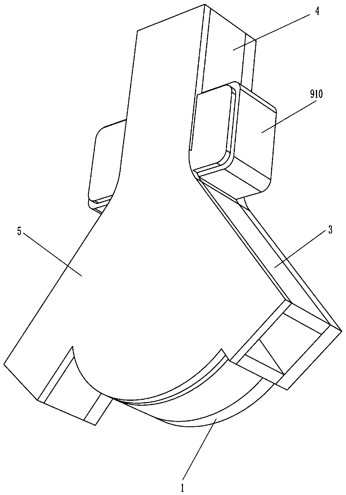
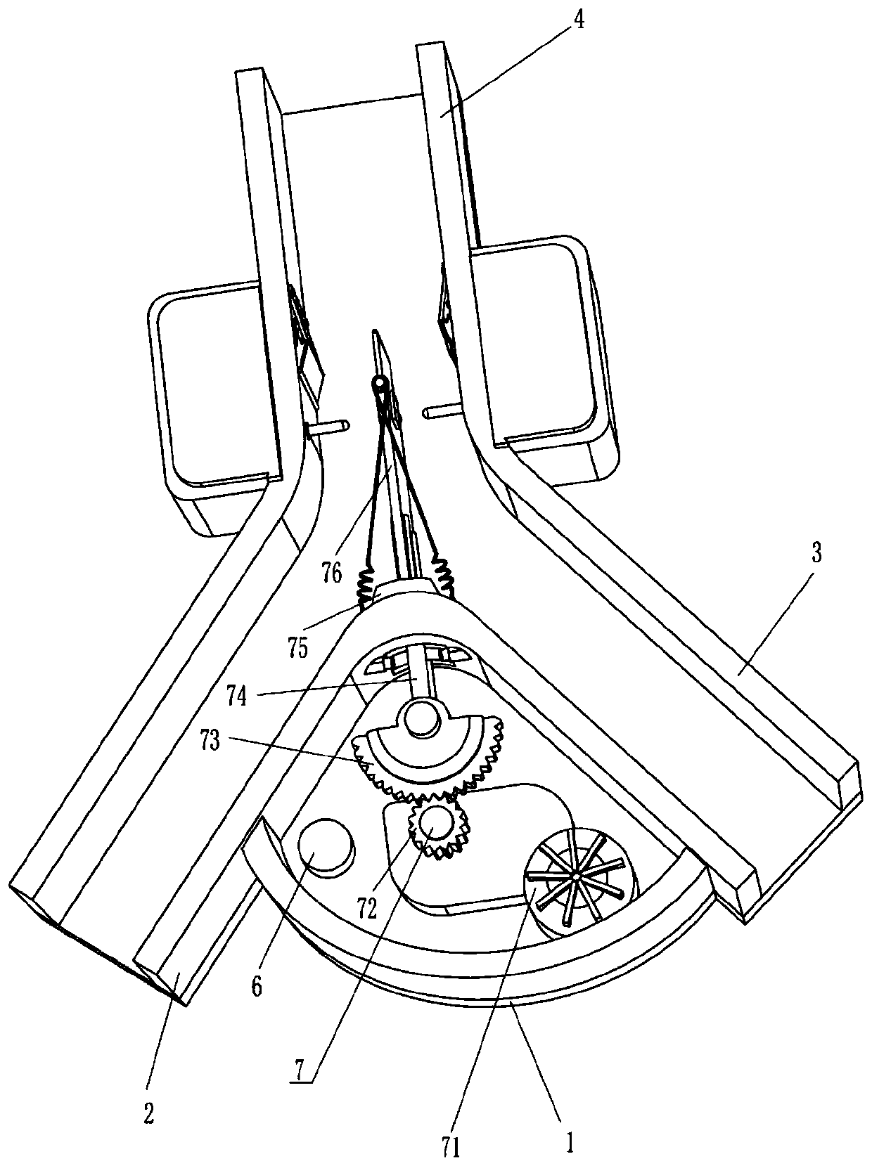
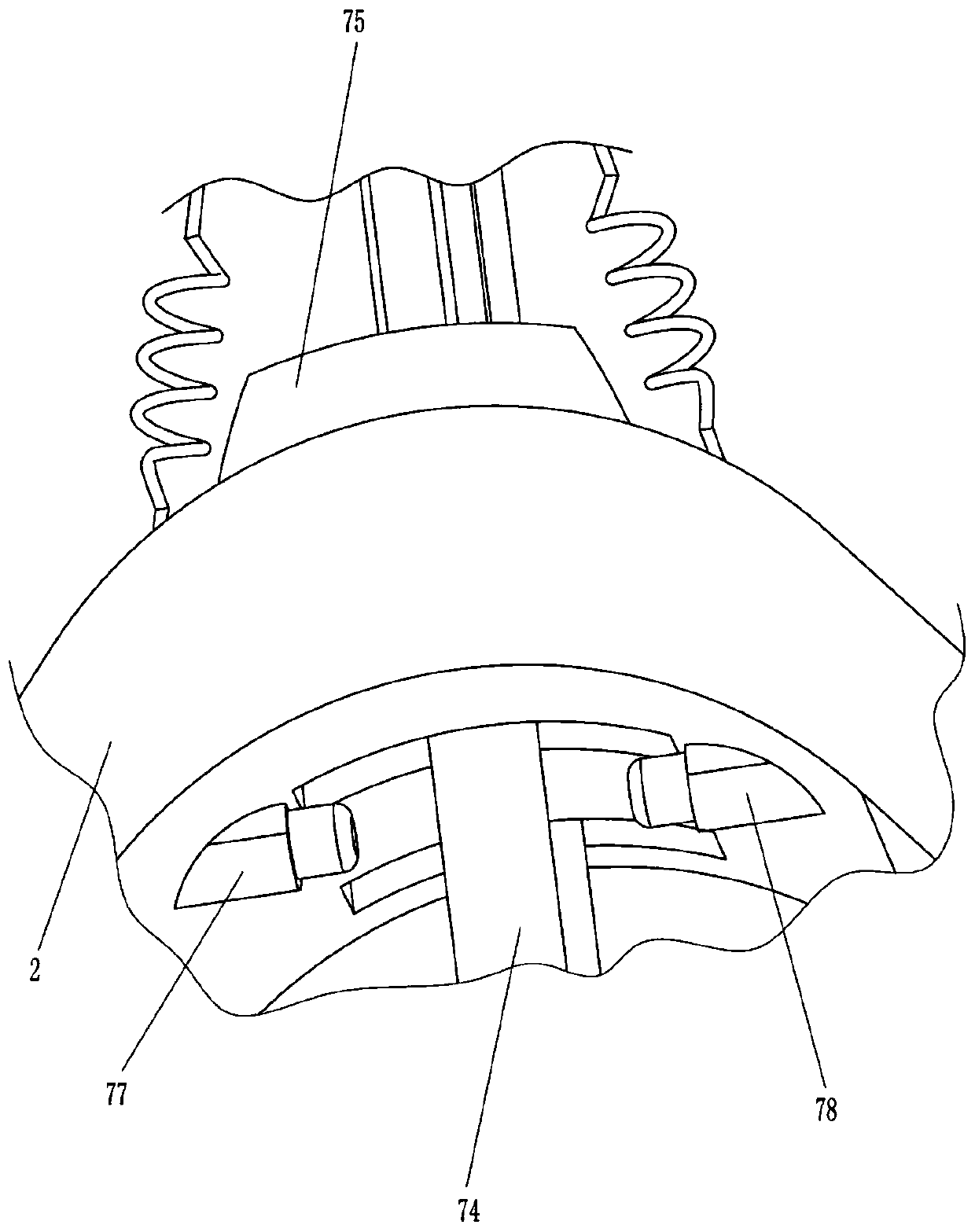
[0029] Such as Figure 1-4 As shown, a rainwater flow equipment for an urban drainage system includes a bottom plate 1, a diverter plate 2, a diverter pipe 3, an inlet pipe 4, a cover plate 5, and a diverter mechanism 7. The bottom plate 1 is connected with a diverter plate 2 at the lower front side, and the bottom plate 1 Split pipes 3 are connected to the left and right sides of the front side. The tops of the two split pipes 3 are connected with an inlet pipe 4. The front side of the inlet pipe 4 and the split pipe 3 are detachably connected with a cover plate 5 through bolts, and the bottom plate 1 is installed There is a shunt mechanism 7.

[0030] It also includes a control module, and the control module and the shunt mechanism 7 are electrically connected.

[0031] The shunt mechanism 7 includes a reduction moto...


PUM


Abstract

The invention discloses rainwater flow dividing equipment for an urban drainage system. The rainwater flow dividing equipment for the urban drainage system comprises a bottom plate, flow dividing plates, flow dividing pipes and the like, wherein the flow dividing plates are fixedly connected to the bottom plate, the flow dividing pipes are fixedly connected to the two sides of the bottom plate, and the flow dividing plates are located between the flow dividing pipes on the two sides. According to the rainwater flow dividing equipment, a flow dividing mechanism can be controlled to divide rainwater through a remote controller, garbage in a water inlet pipe and the flow dividing pipes can be cleaned by opening a cover plate, and therefore the garbage can be rapidly cleaned away, time can besaved, a first gear can be helped to drive a sector gear to rotate through a power assisting mechanism, and therefore abrasion of the first gear and the sector gear can be avoided.

Description

Technical field [0001] The invention relates to a rainwater flow device, in particular to a rainwater flow device for an urban drainage system. Background technique [0002] The drainage system is an important infrastructure of a modern city. In the construction of municipal construction and environmental treatment projects, the drainage system occupies a large proportion of investment. In daily life, people need to use water. After use, the water becomes waste water and the waste water is drained. The system drains to other places. When it rains, the amount of water increases sharply, and people need to drain some of the water to other places. [0003] At present, a part of the water is mainly discharged to other places through valves. There may be some garbage in the water. The internal structure of the valve is more complicated. The garbage in the water may block the valve, and the valve and the pipeline are generally fixed together, so People need to disassemble the pipeline f...

Claims


Application Information

Patent Timeline
Patent Type & Authority Applications(China)
IPC IPC(8): E03F3/04
CPCE03F1/00E03F3/04E03F5/14E03F7/00
Inventor 速玉宝
Owner 广西乾坤环保科技有限公司
Why Eureka
Try Eureka