Metal rod derusting device

A technology of metal rods and sleeves, which is applied to metal processing equipment, devices for coating liquid on the surface, grinding machines, etc., can solve the problems of high labor intensity, poor rust removal quality, and low efficiency, so as to reduce the cost of rust removal, Effect of reducing losses and increasing efficiency

Inactive Publication Date: 2018-09-21
苏州景欣净化彩板有限公司
View PDF0 Cites 15 Cited by
  • Summary
  • Abstract
  • Description
  • Claims
  • Application Information

AI Technical Summary

Problems solved by technology

[0002] Most of the existing metal rod rust removal is to use the high-speed operation of mechanical equipment to throw steel shots with a certain particle size by the centrifugal force of the throwing head. The thrown steel shots collide with the components violently to remove the rust on the steel surface. The method is generally suitable for mass production of metal rods in machinery factories. It is very uneconomical for users to use the above derusting method, while manual derusting uses simple workpieces and is convenient for construction. It is especially suitable for partial derusting on construction sites. However, by using wire brushes and emery cloth to manually remove rust a little bit, not only the labor intensity is high, but also the quality of rust removal is poor and the efficiency is low, and the surface of the derusted metal rod is in contact with the air again, and there is no timely anti-corrosion during rust removal. Rust treatment, will continue to rust, very impractical

Method used


Image

  • Metal rod derusting device
  • Metal rod derusting device
  • Metal rod derusting device

Examples


Embodiment Construction

[0015] Below in conjunction with accompanying drawing and specific embodiment the present invention is described in further detail:

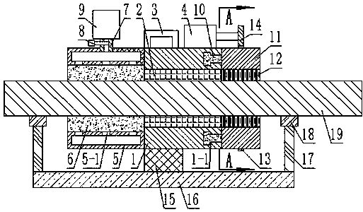
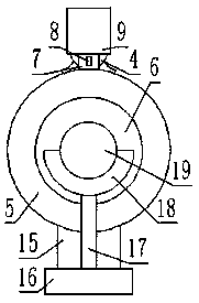
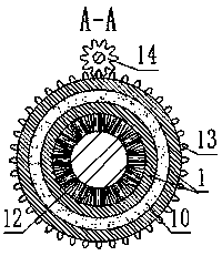
[0016] Such as figure 1 , figure 2 , image 3 As shown, a metal rod derusting device includes a sleeve A1, the inner wall of the sleeve A1 is attached with a rubber layer 2, the top surface of the sleeve A-1 is fixed with a handle 3, and the sleeve A1 A motor 4 is fixed on the top surface of the sleeve A1, and an annular housing 5 is fixed on one side of the sleeve A1. The inner ring surface of the annular housing 5 is uniformly provided with a plurality of through holes 5-1. The annular housing 5 A sponge layer 6 is attached to the inner ring surface of the ring housing 5, and an oil inlet pipe 7 is fixed through the top surface of the annular housing 5, and a valve 8 is arranged in the middle of the oil inlet pipe 7, and an oil tank is fixed on the top surface of the oil inlet pipe 7. 9. The oil tank 9 communicates with the oil inlet pipe ...


PUM


Abstract

The invention discloses a metal rod derusting device. The device comprises a sleeve A, a rubber layer is attached to the inner wall of the sleeve A, a handle is fixed to the top surface of the sleeveA, a motor is fixed to the top surface of the sleeve A, an annular shell is fixed to one side surface of the sleeve A, multiple through holes are evenly formed in the inner annular surface of the annular shell, a sponge layer is attached to the inner annular surface of the annular shell, an oil inlet pipe is fixed to the top surface of the annular shell in a through mode, a valve is arranged on the middle part of the oil inlet pipe, an oil box is fixed to the top surface of the oil inlet pipe, the oil box is communicated with the oil inlet pipe, an annular groove is formed in the other side surface of the sleeve A, and the cross section of the annular groove is T-shaped. According to the device, the oil box and bristles are designed, rust on a metal rod can be fast cleaned off, moreover, through the sponge layer, rust protection treatment is conducted on the derusted metal rod in time, rusting is avoided, loss is reduced, an arranged semi-annular supporting frame can support the metalrod during derusting, use is simple and convenient, time and energy are saved, the derusting cost is reduced, the efficiency is high, and the device is practical and reliable.

Description

technical field [0001] The invention relates to the construction field, in particular to a metal rod derusting device. Background technique [0002] Most of the existing metal rod rust removal is to use the high-speed operation of mechanical equipment to throw steel shots with a certain particle size by the centrifugal force of the throwing head. The thrown steel shots collide with the components violently to remove the rust on the steel surface. The method is generally suitable for mass production of metal rods in machinery factories. It is very uneconomical for users to use the above derusting method, while manual derusting uses simple workpieces and is convenient for construction. It is especially suitable for partial derusting on construction sites. However, by using wire brushes and emery cloth to manually remove rust a little bit, not only the labor intensity is high, but also the quality of rust removal is poor and the efficiency is low, and the surface of the deruste...

Claims


Application Information

Patent Timeline
Patent Type & Authority Applications(China)
IPC IPC(8): B24B27/033B08B1/02B05C1/06B05C11/10
CPCB24B27/033B05C1/06B05C11/10B08B1/005B08B1/02
Inventor 王俊
Owner 苏州景欣净化彩板有限公司
Why Eureka
Try Eureka