Eureka AIR delivers breakthrough ideas for toughest innovation challenges, trusted by R&D personnel around the world.

A transformer respirator system

A respirator and transformer technology, applied in the field of transformers, can solve problems such as tripping of circuit breakers on all sides of transformers, main transformer outage, heavy gas action, etc.

Active Publication Date: 2021-12-31
SHENZHEN POWER SUPPLY BUREAU
View PDF3 Cites 0 Cited by
  • Summary
  • Abstract
  • Description
  • Claims
  • Application Information

AI Technical Summary

Problems solved by technology

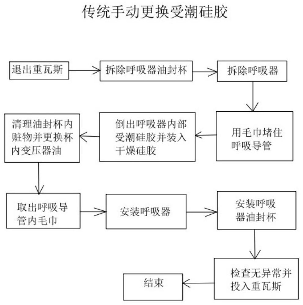
[0005] The present invention aims to propose a transformer respirator system to solve the technical problem that when the existing transformer respirator is replaced and removed, it is easy to cause heavy gas action, causing the circuit breakers on each side of the transformer to trip and the main transformer to stop operating

Method used


Image

  • A transformer respirator system
  • A transformer respirator system
  • A transformer respirator system

Examples


Embodiment Construction

[0046] Various exemplary embodiments, features, and aspects of the present disclosure will be described in detail below with reference to the accompanying drawings. The same reference numbers in the figures indicate functionally identical or similar elements. While various aspects of the embodiments are shown in drawings, the drawings are not necessarily drawn to scale unless specifically indicated.

[0047] In addition, in order to better illustrate the present invention, numerous specific details are given in the following specific examples. It will be understood by those skilled in the art that the present invention may be practiced without certain of the specific details. In some instances, means, elements and circuits well known to those skilled in the art have not been described in detail so as to highlight the gist of the present invention.

[0048] An embodiment of the present invention proposes a transformer respirator system. The transformer respirator system in th...


PUM


Abstract

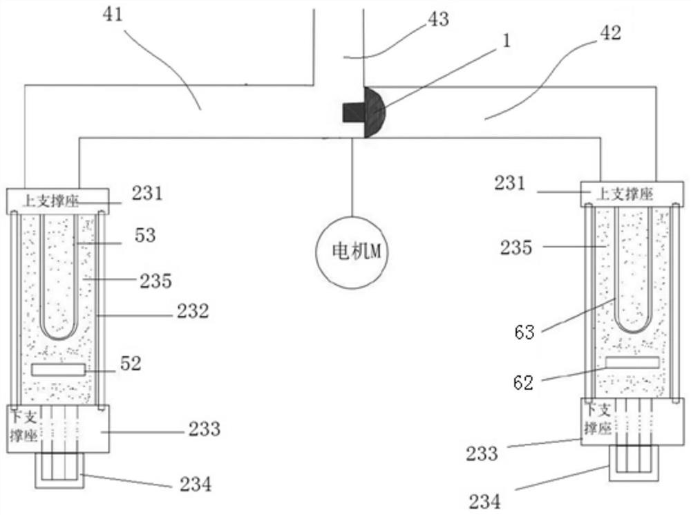
The present invention provides a transformer respirator system, which includes a control unit, a driving mechanism, a three-way conduit, and a linkage valve. The three-way conduit includes a connected first conduit, a second conduit, and a third conduit. The linkage valve is arranged at The connection of the first conduit, the second conduit and the third conduit, the opening side of the first conduit is connected to the first respirator, the opening side of the second conduit is connected to the second respirator, and the opening side of the third conduit is connected to the transformer For an oil conservator, the control unit is used to control the driving mechanism to drive the linked valve so as to make the first conduit, the second conduit and the third conduit conduct or block. The invention can solve the technical problem that heavy gas action is easily caused when the existing transformer respirator is replaced and removed, and the circuit breakers on each side of the transformer are tripped and the main transformer is out of operation.

Description

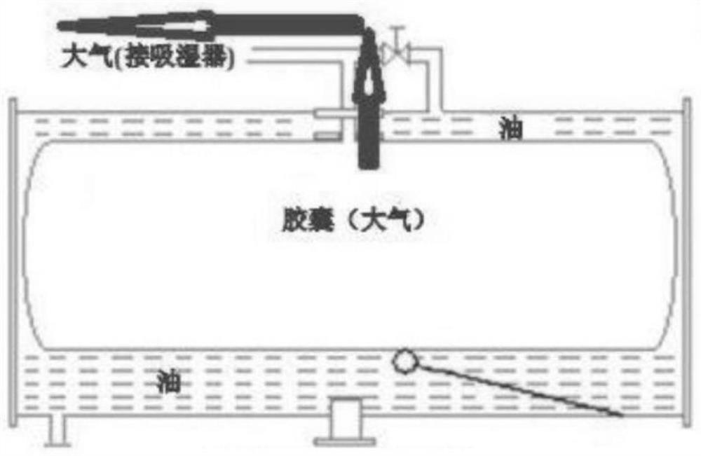
technical field [0001] The invention relates to the technical field of transformers, in particular to a transformer respirator system. Background technique [0002] During the normal operation of the transformer, the transformer needs to exchange gas with the outside world, so as to ensure the normal oil level in the transformer oil tank. The breather is installed at the end of the pipeline where the oil conservator communicates with the air. When the temperature of the transformer rises, the oil in the oil tank will expand accordingly, so the oil level in the oil conservator will also rise accordingly, and at this time, part of the gas in the capsule will be discharged through the respirator. When the temperature of the transformer drops, the oil in the oil tank will shrink accordingly, so the oil level in the oil conservator will also decrease accordingly, and at this time, the capsule inhales part of the gas through the respirator. So the respirator is one of the very i...

Claims


Application Information

Patent Timeline
Patent Type & Authority Patents(China)
IPC IPC(8): H01F27/14H01F27/40
CPCH01F27/14H01F27/40H01F27/402H01F2027/406
Inventor 岑凯辛龚福维高瑞鑫
Owner SHENZHEN POWER SUPPLY BUREAU
Why Eureka
Eureka Blog
Learn More