Shooting angle control method, terminal and storage medium

A technology of shooting angle and control method, which is applied to the parts and electrical components of TVs and color TVs, can solve the problems of fixed shooting angles, inability to bring convenience to users' daily life, and limited use scenarios of camera equipment, so as to achieve good shooting. effect of effect

Active Publication Date: 2020-06-19
SHENZHEN SKYWORTH RGB ELECTRONICS CO LTD
View PDF7 Cites 3 Cited by
  • Summary
  • Abstract
  • Description
  • Claims
  • Application Information

AI Technical Summary

Problems solved by technology

[0002] In recent years, new smart TVs have been equipped with camera equipment, which improves the user experience; due to the differences between TVs and mobile terminals such as mobile phones, TVs are inconvenient to move the shooting angle, and thus cannot achieve better shooting results ; Moreover, the shooting angle of the camera equipment on the TV is fixed, so that the shooting effect cannot achieve good results
[0003] As the function of TV increases, if it is only used to watch programs, it can no longer meet the needs of daily life; therefore, the increased camera equipment can help users' daily life, for example, video telephony; however, the camera fixed on the TV The usage scenarios of the device are limited, resulting in a small application range of the camera device; except for watching TV, the camera device should have more application scenarios, but it is limited to the fixed scene of the TV and cannot provide more services. At the same time, the smart TV As an important part of the current smart home appliances, it takes up a lot of home space, but many of its functions have not been well applied, and cannot bring convenience to users' daily life

Method used


Image

  • Shooting angle control method, terminal and storage medium
  • Shooting angle control method, terminal and storage medium
  • Shooting angle control method, terminal and storage medium

Examples


Embodiment 1

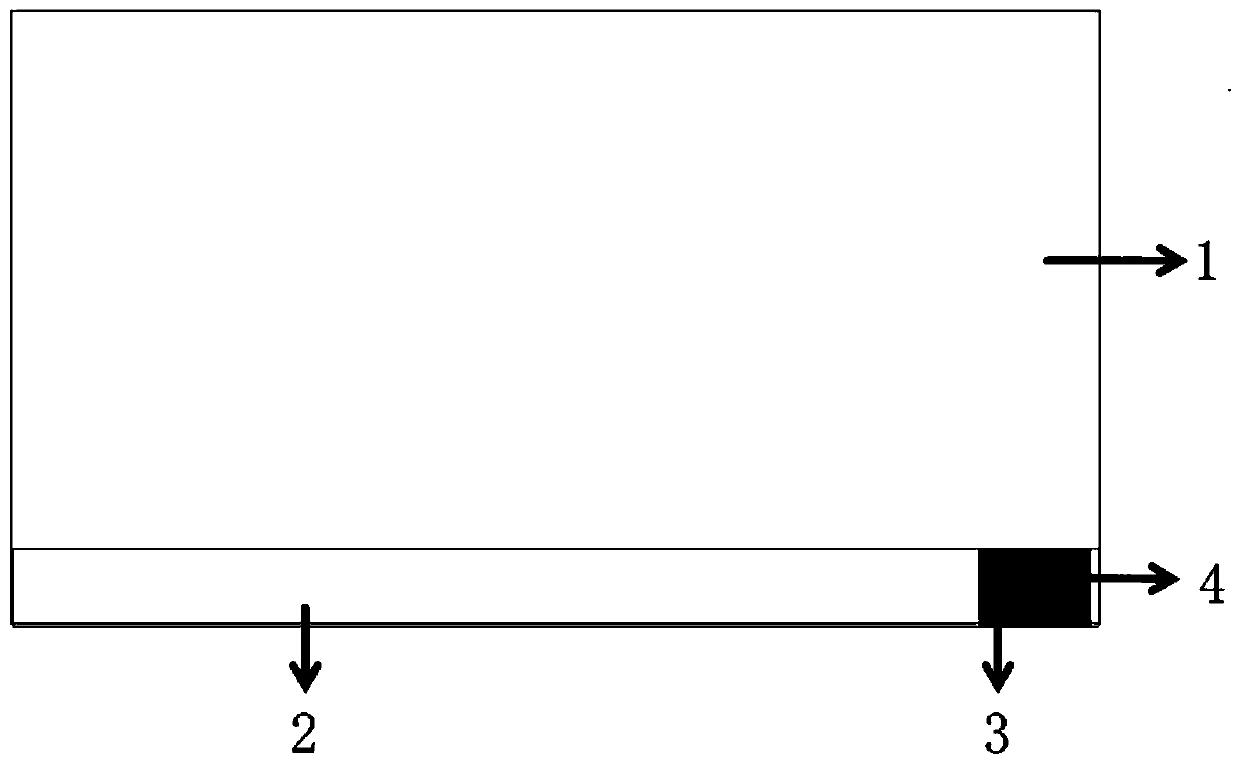
[0054] At present, some terminals are equipped with cameras, such as smart TVs, such as image 3 As shown, the smart TV has added a camera module. At the same time, the smart TV also has the characteristics of network, far-field voice, powerful processor and large-capacity storage; however, due to the fixed method of the traditional camera module and the lack of related applications The program, therefore, can only display the image from the camera on the screen, without a good combination of the two.

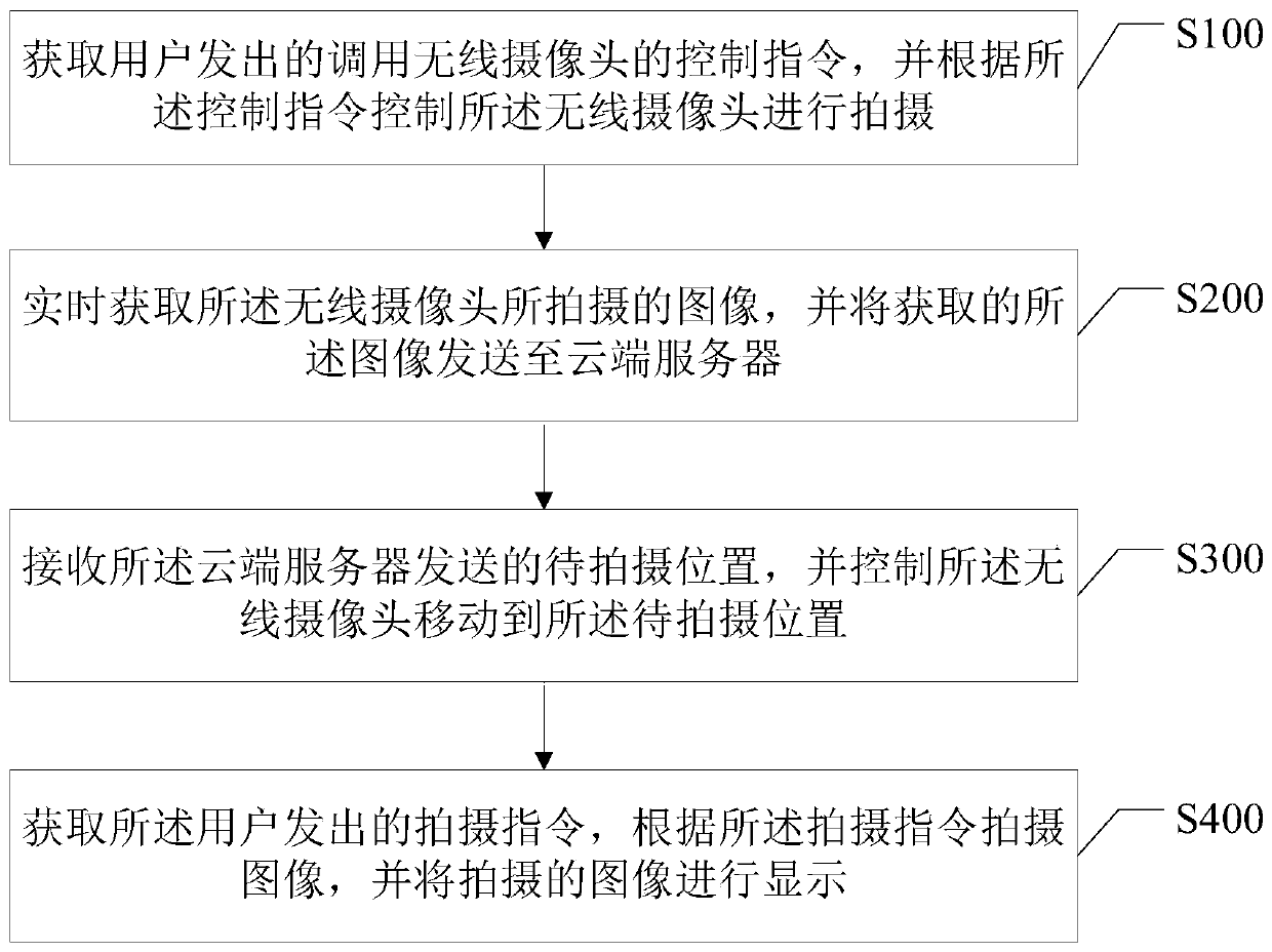
[0055] In order to better combine the camera and the terminal so that the camera can shoot better, this embodiment provides a shooting angle control method to solve the problem that the camera of the terminal has a bad shooting angle, cannot be moved, cannot be used remotely, and cannot be used remotely. Intelligently identify the problem of adjusting the shooting angle of the portrait, so as to effectively use the shape and functions of the terminal (for example, remote monito...

Embodiment 2

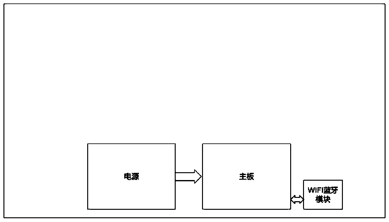
[0134] Such as Figure 11 As shown, this embodiment provides a terminal, including a display screen, a power supply (that is, a power supply system 70), a motherboard, and a WiFi network port module 90, wherein the terminal further includes: a wireless camera 10, a magnetic mobile device 20, a wireless Charging module 30, processor 50, memory 40, voice control module 60 and communication interface 80;

[0135] The wireless camera 10 is connected to the WiFi network port module 90 through a wireless network; the magnetic mobile device 20 is connected to the processor 50 and magnetically connected to the wireless camera 10; the wireless charging module 30 is connected to the The power supply is connected; the memory 40 is connected to the processor 50;

[0136] The wireless camera 10 is used to capture images and transmit the images to the processor 50;

[0137] The magnetic attraction moving device 20 is used to move the wireless camera 10 to an initial position, or to move t...

Embodiment 3

[0141] This embodiment provides a storage medium, wherein the storage medium stores a shooting angle control program, and when the shooting angle control program is executed by a processor, it is used to implement the operation of the shooting angle control method as described in Embodiment 1; Specifically as above.

[0142] To sum up, when the user uses the wireless camera, the present invention can intelligently identify the content of the image according to the images captured by the wireless camera, and use the magnetic moving device of the terminal to move the wireless camera to a designated position, so that the wireless camera can obtain better shooting angle to achieve a better shooting effect; at the same time, the wireless camera can be split and placed at any position according to actual needs; in addition, the present invention can control the mobile angle of the wireless camera on the terminal screen through the application program of the mobile terminal, Realize ...


PUM


Abstract

The invention discloses a shooting angle control method, a terminal and a storage medium, and the shooting angle control method comprises the steps: obtaining a control instruction which is sent by auser and is used for calling a wireless camera, and controlling the wireless camera to carry out the shooting according to the control instruction; acquiring an image shot by the wireless camera in real time, and sending the acquired image to a cloud server; receiving a to-be-photographed position sent by the cloud server, and controlling the wireless camera to move to the to-be-photographed position; and obtaining a shooting instruction sent by the user, shooting an image according to the shooting instruction, and displaying the shot image. According to the invention, the image shot by the wireless camera is uploaded to the cloud server for analysis, the optimal shooting angle is obtained through calculation, and then the position of the wireless camera is moved to the optimal shooting position by using the magnetic attraction moving device in the terminal, so that the problem of poor shooting angle caused by incapability of moving of a traditional camera is solved.

Description

technical field [0001] The present invention relates to the field of terminal applications, in particular to a shooting angle control method, a terminal and a storage medium. Background technique [0002] In recent years, new smart TVs have been equipped with camera equipment, which improves the user experience; due to the differences between TVs and mobile terminals such as mobile phones, TVs are inconvenient to move the shooting angle, and thus cannot achieve better shooting results ; Moreover, the shooting angle of the camera equipment on the TV is fixed, so that the shooting effect cannot achieve a good effect. [0003] As the function of TV increases, if it is only used to watch programs, it can no longer meet the needs of daily life; therefore, the increased camera equipment can help users' daily life, for example, video telephony; however, the camera fixed on the TV The usage scenarios of the device are limited, resulting in a small application range of the camera de...

Claims


Application Information

Patent Timeline
Patent Type & Authority Applications(China)
IPC IPC(8): H04N5/232
CPCH04N23/661H04N23/695
Inventor 徐正新卢铁军姚文兴廖燕辉黄健陈敏胡超
Owner SHENZHEN SKYWORTH RGB ELECTRONICS CO LTD
Why Eureka
Try Eureka