An image recognition system for archives informatization archiving

An image recognition and file technology, applied in the field of image recognition system, can solve problems such as difficult maintenance, achieve the effect of improving clarity, ensuring fixed quality, and realizing online standardized management

Pending Publication Date: 2019-02-26
STATE GRID ZHEJIANG CIXI POWER SUPPLY +1
0 Cites 1 Cited by

AI-Extracted Technical Summary

Problems solved by technology

[0004] The technical problem to be solved by the present invention is to provide an image recognition system for file infor...

Method used

At last, described horizontal cross bar 20 is provided with the rotating sleeve 4 of installing camera 3, realizes that camera 3 is installed on horizontal cross bar 20 by rotating sleeve 4, adjusts camera 3 on horizontal cross bar 20 by rotating sleeve 4 The above installation angle, thereby changed the shooting angle of the camera 3, can make the shooting area of ​​the camera 3 reach the best, and ensure the clarity and flatness of the data image; the camera 3 is connected to the PC 30 through a USB connection line 31, The horizontal bar 20 is provided with a placement groove 29 for placing the USB connection line 31, the USB connection line can realize the quick connection of the camera and the PC, ensuring the fast transmission of data, and the placement groove can realize the unified placement of the USB connection line 31, Avoiding the loss and damage of the USB connection line 31, ensuring that the operator can quickly find the USB connection line 31 at the first time; the base 1 is also provided with a pole 5, and the pole 5 is covered with a fixing plate 51 , the marking layer 13 is arranged on the fixing plate 51, and the marking layer 13 can be fixedly arranged on the base 1 through the vertical rod 5 and the fixing plate 51, thereby avoiding the loss and damage of the marking layer 13, and ensuring that the marking layer 13 can be in order Marking is beneficial for storage and subsequent verification.
Described support 2 comprises horizontal bar 20 and vertical bar 21, and described vertical bar 21 comprises fixed bar 22 and movable bar 23, and described fixed bar 22 is arranged on the base 1, and described horizontal bar 20 is arranged on On movable bar 23, described fixed bar 22 is provided with the electric push rod 24 that links to each other with movable bar 23, and support is set to horizontal bar and vertical bar, is conducive to the fast installation and fixing of camera 3, and vertical bar 21 is set to The fixed rod 22 and the movable rod 23 can adjust the height of the vertical rod 21 according to different files 6. The practical performance is good, and the height adjustment of the movable rod 23 on the fixed rod 22 can be realized by the electric push rod 24, and the vertical rod 21 can b...

Abstract

The invention relates to an image recognition system for archives informatization archiving, comprising a base and a bracket. The base comprises a positioning slot and a stopper. A camera is arrangedon the bracket, a USB connecting cable is arranged on the camera, an identification layer is arranged on the base, and a bar code is arranged on the identification layer. Advantages of the invention:the files to be archived are placed in the positioning slot through the positioning slot, and then locking the file in the positioning groove through the stopper. Then the archives are photographed bythe camera, and the archives photographed by the camera are archived by the USB connection line. The advantages of the method are as follows: the digital, text and color signature on the archives canbe compared with the standard signature template, and the key information of text, signature and signature can be automatically extracted; the key information of the digital, text and color signatureon the archives can be extracted; the paperless archives information system is eralized, the online standardized management of engineering projects is realized, for overdue, risk projects, early warning and warning are provided, later combined with the knowledge base, the corresponding solutions can be given automatically.

Application Domain

Character and pattern recognitionDocument management systems

Technology Topic

Information systemBarcode +8

Image

  • An image recognition system for archives informatization archiving
  • An image recognition system for archives informatization archiving

Examples

  • Experimental program(1)

Example Embodiment

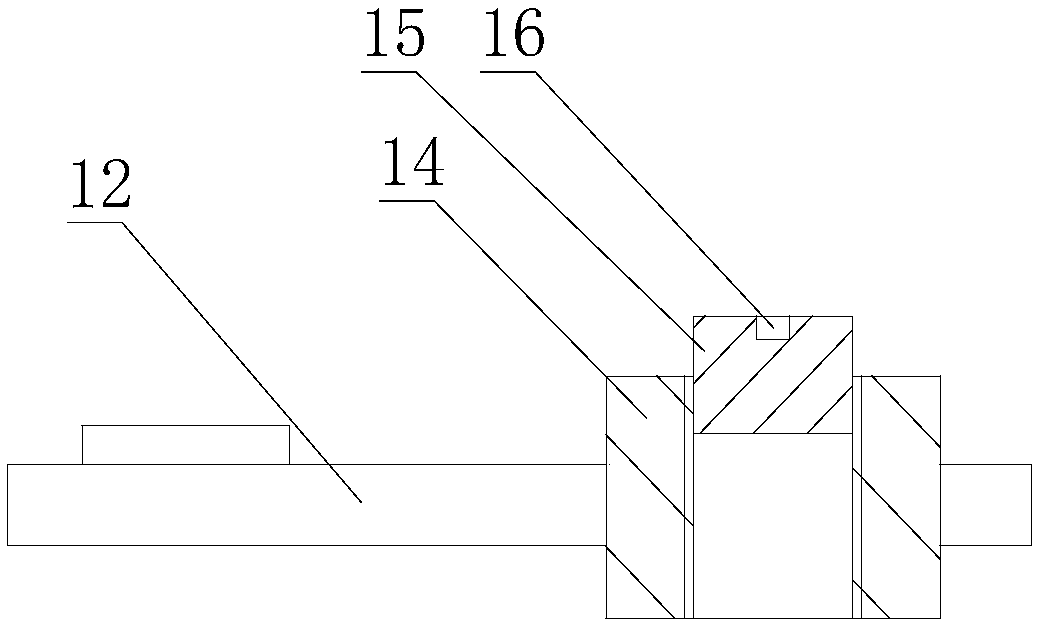
[0025] Such as figure 1 , figure 2 As shown, an image recognition system for file information filing includes a base 1 and a bracket 2 set on the base 1. The base 1 includes a positioning slot 11 for placing the file 6 and locking the file 6 In the baffle 12 in the positioning groove 11, the bracket 2 is provided with a camera 3 for shooting files 6. The vertical axis of the camera 3 coincides with the vertical axis of the positioning groove 11, and the vertical axis of the camera The axis coincides with the vertical axis of the positioning groove, which can ensure that the camera has the best shooting angle for shooting, improve the clarity of file information filing, and facilitate subsequent operators to quickly read information. The camera 3 is connected to The PC 30, the base 1 is also provided with an identification layer 13 adhered to the file 6, and the identification layer 13 is provided with a bar code. When in use, the file to be archived is placed in the positioning slot through the positioning slot. Then lock the file in the positioning slot through the stopper, and then realize the shooting processing of the file through the camera, and then use the USB cable to archive the file captured by the camera. It has the following advantages: Sign text and color, compare standard signature templates, automatically extract key information of text, signature, and signature; realize a paperless file information system, realize online standard management of engineering projects, and provide early warning and warning for overdue and risky projects Warning, in the later stage, combined with the knowledge base, the corresponding solution suggestions can be automatically given; and by sticking the identification layer with barcode on the archive, it can be saved in the file format of the barcode and saved in the PC. The follow-up The barcode information can be searched through the PC, and the key information can be automatically extracted, and the project name and the location of the project chapter to which this identification chapter belongs can be distinguished, so as to realize rapid filing. All the archives of the project and the key signature can be extracted later. And signed letter.
[0026] In addition, one end of the baffle 12 is rotatably connected to the base 1, and the other end of the baffle 12 is provided with a pressing block 14 in contact with the file 6. By setting one end of the baffle 12 to be rotatably connected to the base 1, It is quickly realized that the file 6 is placed in the positioning slot 11, and the file 6 is pressed by the pressing block 14 at the other end of the stopper 12, which can ensure the fixed quality of the file 6 and the flatness of the file 6 when the camera 3 shoots. The other end of the stopper 12 is provided with a threaded hole, the pressure block 14 is provided with an external thread that matches the threaded hole, and the top of the pressure block 14 is provided with an upwardly extending boss 15 which is provided with There is a connecting hole 16 for connecting a wrench, and the pressure block 14 is installed and adjusted on the baffle 12 through threads, which can be adjusted according to the files 6 of different thicknesses, and the setting of the boss 15 is beneficial to the operation of the operator.
[0027] The bracket 2 includes a horizontal crossbar 20 and a vertical rod 21. The vertical rod 21 includes a fixed rod 22 and a movable rod 23. The fixed rod 22 is disposed on the base 1 and the horizontal crossbar 20 is disposed on the movable rod 23. Above, the fixed rod 22 is provided with an electric push rod 24 connected to the movable rod 23, and the bracket is set as a horizontal horizontal rod and a vertical rod, which is beneficial to the quick installation and fixation of the camera 3, and the vertical rod 21 is configured as a fixed rod 22 And the movable rod 23 can adjust the height of the vertical rod 21 according to different files 6, which has good practical performance, and the height adjustment of the movable rod 23 on the fixed rod 22 is realized through the electric push rod 24, which can realize the automatic adjustment of the vertical rod 21 , The use effect is good, the fixed rod 22 is provided with a fixed groove 25 for installing the electric push rod 24, the movable rod 23 is provided with a connecting groove 26, and the piston rod of the electric push rod 24 is provided with a connecting block 27 The connecting block 27 facing the end of the connecting groove 26 is provided with a magnet 28, the movable rod is a magnetic rod, and the electric push rod 24 is installed on the fixed rod 22 through the fixed groove 25, which can prevent the electric push rod 24 from being exposed In the air, the service life of the electric push rod 24 is increased, and the piston rod of the electric push rod 24 is connected with the movable rod 23 through the connecting block 27 with the magnet 28, which can ensure that the electric push rod 24 and the movable rod 23 are connected. It is reliable, and the connecting groove 26 is provided on the movable rod 23, which can make the piston rod play a guiding role during the lifting process, ensure the stability of the movable rod 23 ascending and descending, and reduce the vibration of the camera 3 during the lifting process.
[0028] Finally, the horizontal bar 20 is provided with a rotating sleeve 4 for installing the camera 3, the camera 3 is installed on the horizontal bar 20 by rotating the sleeve 4, and the installation of the camera 3 on the horizontal bar 20 is adjusted by rotating the sleeve 4 The camera 3’s shooting angle is changed, and the shooting area of ​​the camera 3 can be optimized to ensure the clarity and flatness of the data image; the camera 3 and the PC 30 are connected through the USB cable 31, and the horizontal The cross bar 20 is provided with a slot 29 for placing the USB cable 31. The USB cable can realize the fast connection between the camera and the PC and ensure the rapid transmission of data. The slot can realize the unified placement of the USB cable 31, avoiding USB The loss and damage of the connecting line 31 ensure that the operator can quickly find the USB connecting line 31 in the first time; the base 1 is also provided with an upright 5, and the upright 5 is covered with a fixing plate 51. The identification layer 13 is arranged on the fixed plate 51, and the identification layer 13 can be fixedly arranged on the base 1 through the pole 5 and the fixed plate 51, which avoids the loss and damage of the identification layer 13 and ensures that the identification layer 13 can be marked in order. Conducive to storage and subsequent verification.
[0029] In addition to the above-mentioned preferred embodiments, the present invention has other embodiments. Those skilled in the art can make various changes and modifications according to the present invention. As long as they do not deviate from the spirit of the present invention, they should all be defined by the appended claims of the present invention. range.

PUM

no PUM

Description & Claims & Application Information

We can also present the details of the Description, Claims and Application information to help users get a comprehensive understanding of the technical details of the patent, such as background art, summary of invention, brief description of drawings, description of embodiments, and other original content. On the other hand, users can also determine the specific scope of protection of the technology through the list of claims; as well as understand the changes in the life cycle of the technology with the presentation of the patent timeline. Login to view more.

Similar technology patents

Electric vehicle charging equipment with wind-proof function

InactiveCN109747459Aimprove clarityReduce the chance of misuse
Owner:SHENZHEN BEIYOUTONG NEW ENERGY TECH DEV CO LTD

Light-control flexible semiconductor terahertz wave space modulator

InactiveCN109489815Aimprove clarityreduce transmittance
Owner:UNIV OF ELECTRONIC SCI & TECH OF CHINA

Classification and recommendation of technical efficacy words

  • improve clarity

Curved surface defect automatic detection method and apparatus thereof

ActiveCN106127780Aimprove clarityBig amount of data
Owner:SOUTH CHINA UNIV OF TECH

Imaging device of large geotechnical centrifuge

InactiveCN101917552Aimprove clarityfull of information
Owner:SOUTHWEST JIAOTONG UNIV

Prismatic AR (Augmented Reality) display device

PendingCN107422484Asmall color differenceimprove clarity
Owner:GOERTEK OPTICAL TECH CO LTD
Why Eureka
Try Eureka