Pneumatic window-breaking clamping device at top end of rescue aerial ladder truck
A technology of clamping device and aerial ladder vehicle, which is applied in the direction of ladders, life-saving equipment, building rescue, etc., can solve the problems of single function and inconvenient use of high-altitude rescue gondola, so as to improve the reliability of rescue, maintain stability, reduce the The effect of small fears
- Summary
- Abstract
- Description
- Claims
- Application Information
AI Technical Summary
Problems solved by technology
Method used
Image
Examples
Embodiment 1
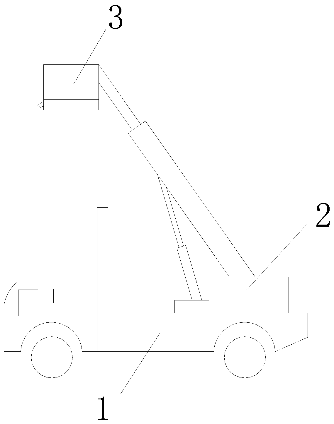
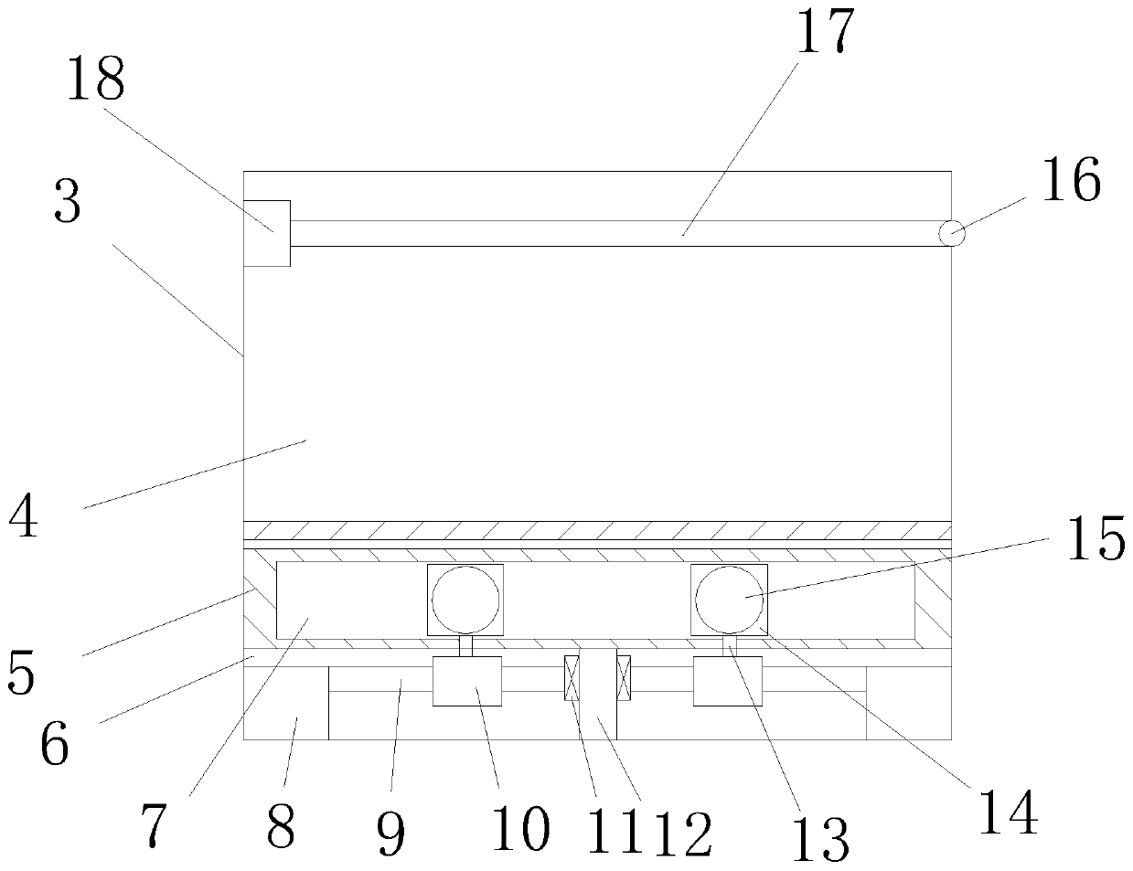
[0047] Embodiment one, with reference to Figure 1~2 and 4-10, a pneumatic window-breaking clamping device at the top of a rescue aerial ladder vehicle 1, including a aerial ladder vehicle 1, an aerial ladder mechanism 2 is arranged on the aerial ladder vehicle 1, and a hanging basket 3 is fixedly installed on the top of the aerial ladder mechanism 2, and the hanging basket 3 includes The basket frame 4 is provided with an organic compartment 6 at the bottom of the basket frame 4. The window-breaking clamping mechanism is arranged on the compartment 6. The window-breaking clamping mechanism includes a symmetrically arranged convenient impact cylinder mechanism. The front end of the convenient impact cylinder mechanism is provided with a punching mechanism. Rod 20, the outer end of the punch rod 20 is connected with a window-breaking clamping hammer 19; the window-breaking clamping hammer 19 is in the shape of a conical arrow, and the horizontal length of the window-breaking cla...
Embodiment 2
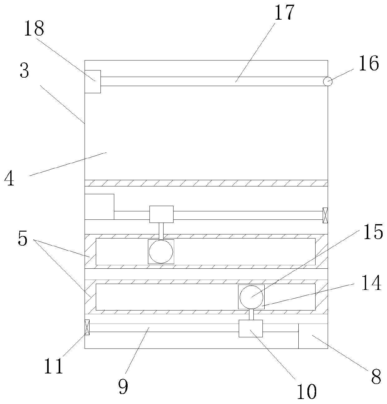
[0052] Embodiment two, refer to image 3 , the difference between this embodiment and Embodiment 1 is:
[0053] Wherein, two sliding seats 5 at the front end of the machine compartment 6 are arranged in parallel up and down, and the two sliding seats 5 are respectively fitted with a polygonal sliding storehouse 14, and the top of the upper sliding seat 5 and the lower sliding seat 5 The bottom of the bottom is respectively provided with a screw drive mechanism, so that the upper and lower polygonal sliding bins 14 are staggered and arranged to facilitate mutual approaching and clamping.
Embodiment 3
[0054] Embodiment three, refer to Figures 11 to 13 The difference between this embodiment and Embodiment 1 is that: the hanging basket 3 is provided with an escape chute bag; the two sides of the hanging basket 3 are provided with an escape chute bag rewinding mechanism, and the escape chute bag rewinding mechanism includes The roller frame 32, the roller frame 32 is installed obliquely above the top of the side of the hanging basket 3, the side of the hanging basket 3 is provided with a bag entrance frame 27, and the bag roller 29 is equipped with an escape slide bag 28, and one end of the escape slide bag 28 is connected to the bag On the entrance frame 27, the other end is wound on the cloth bag roller 29 in an orderly manner. After completion, one end of the inner side is connected with the bag inlet frame 27 as the inlet port; one end of the outer side is used as the outlet port on the ground; Tied to the top of the hanging basket 3, by untying the pull rope 33, the esc...
PUM
 Abstract
Description
Claims
Application Information
 - R&D
- Intellectual Property
- Life Sciences
- Materials
- Tech Scout
- Unparalleled Data Quality
- Higher Quality Content
- 60% Fewer Hallucinations
Browse by: Latest US Patents, China's latest patents, Technical Efficacy Thesaurus, Application Domain, Technology Topic, Popular Technical Reports.
© 2025 PatSnap. All rights reserved.Legal|Privacy policy|Modern Slavery Act Transparency Statement|Sitemap|About US| Contact US: help@patsnap.com


