Linkage mud feeding device for aluminum pot mold manufacturing

A mold and aluminum pot technology, applied in the field of aluminum pot billet, can solve the problems of poor structure, slowness, low efficiency, etc., and achieve the effect of reasonable device structure and obvious linkage effect

Inactive Publication Date: 2020-06-26
周小红
View PDF10 Cites 4 Cited by
  • Summary
  • Abstract
  • Description
  • Claims
  • Application Information

AI Technical Summary

Problems solved by technology

[0004] The structure is poor and the efficiency is low. At present, when making billets, it is necessary to manually put mud and scrape manually. The whole process is extre

Method used


Image

  • Linkage mud feeding device for aluminum pot mold manufacturing
  • Linkage mud feeding device for aluminum pot mold manufacturing
  • Linkage mud feeding device for aluminum pot mold manufacturing

Examples


Example Embodiment

[0032] Example 1

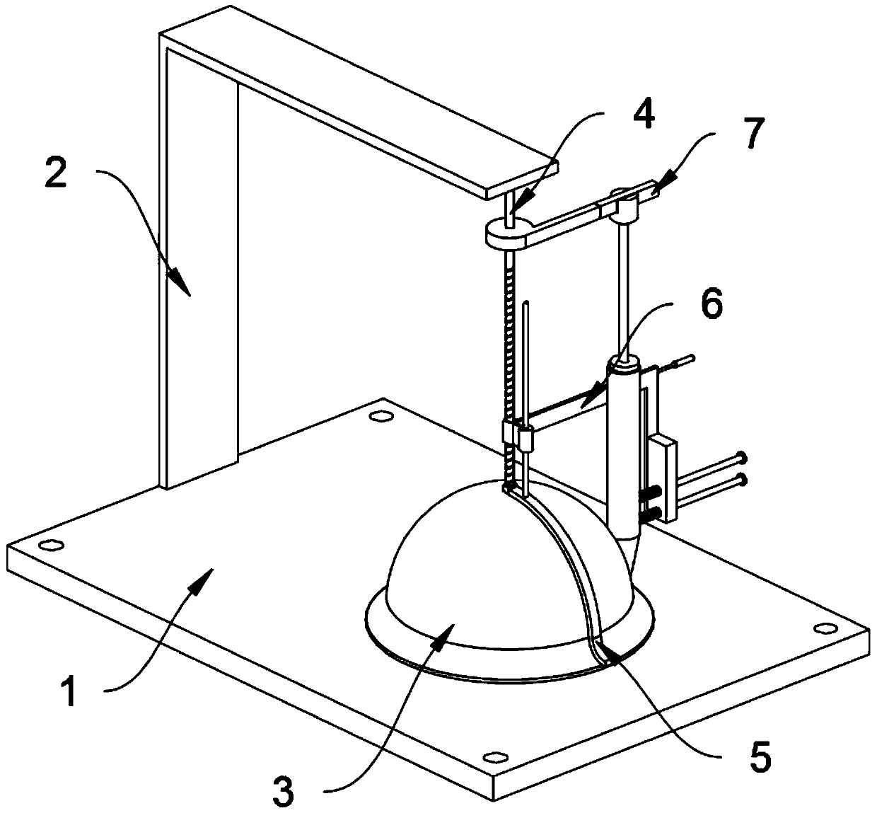
[0033] as attached figure 1 to attach Figure 8 Shown:

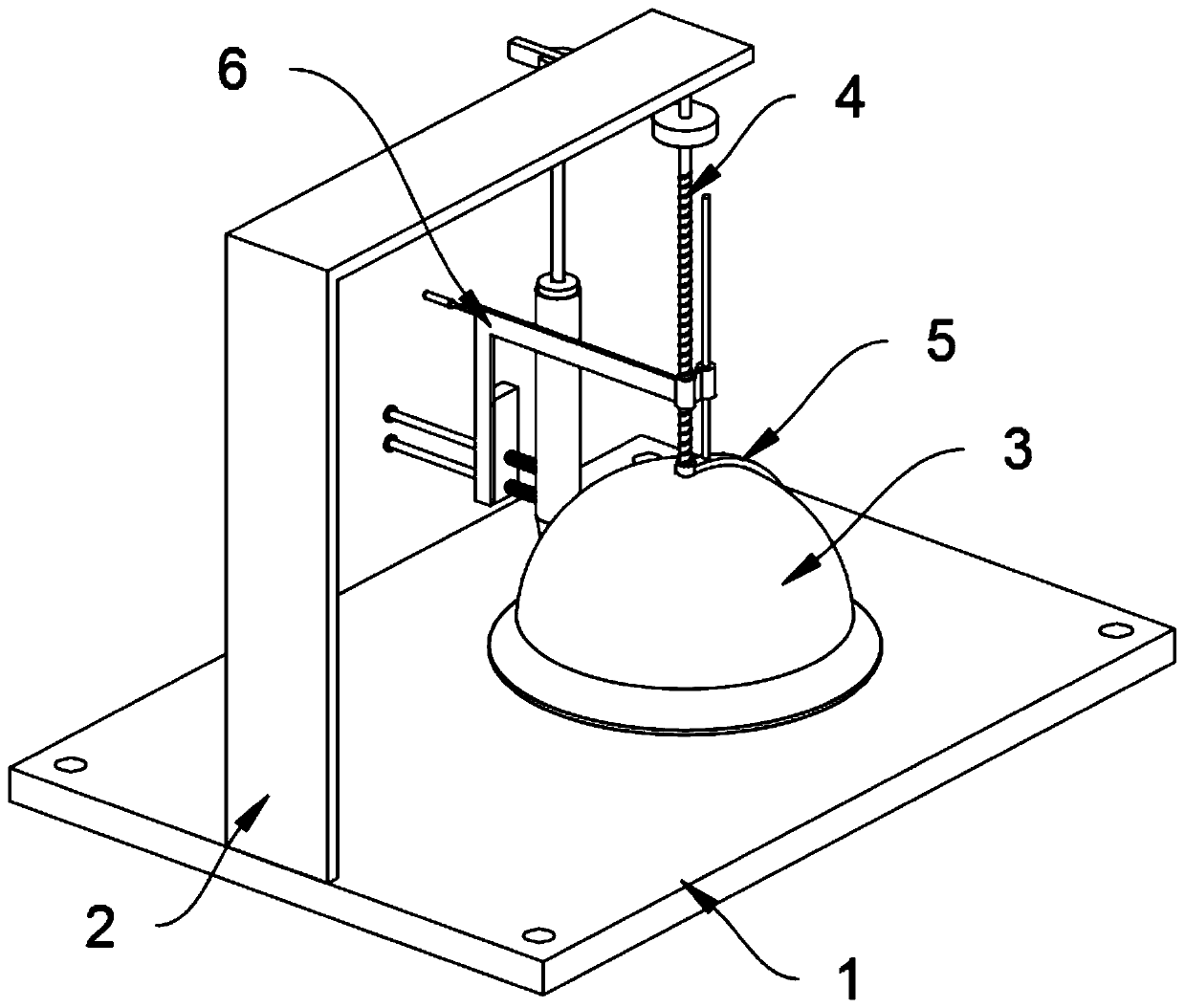
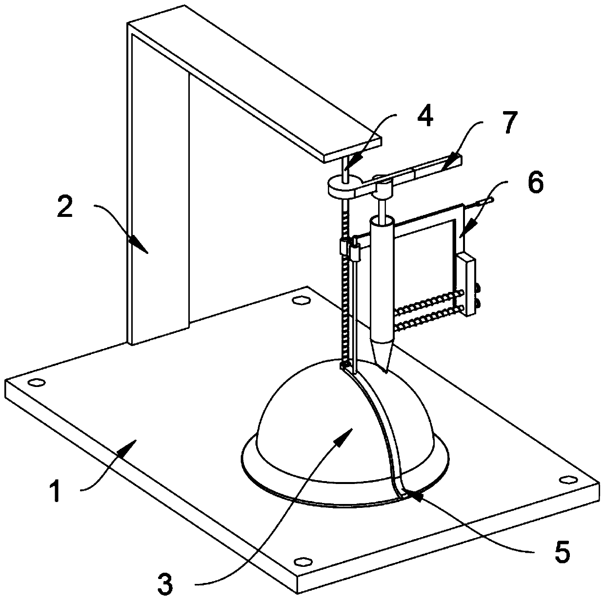
[0034] The present invention provides a linkage claying device for making aluminum pot moulds, comprising a base 1; a mounting frame 2 is welded on the left side of the top of the base 1, a pot body 3 is placed on the right side of the top of the base 1, and a screw thread is installed on the top of the mounting frame 2 in a rotating manner The rod 4 is rotatably connected with a scraper structure 5 at the bottom end of the threaded rod 4, and the threaded rod 4 is provided with a mud feeding structure 6 and an extruding rod structure 7.

[0035] When in use, first pour the soil into the upper mud structure 6, then turn the upper mud structure 6, the extrusion rod structure 7 squeezes the mud in the upper mud structure 6, and apply the mud in the upper mud structure 6 on the pot body 3 , The scraper structure 5 can scrape the soil flat.

Example Embodiment

[0036] Example 2

[0037] Reference as image 3 and Figure 4 The upper mud structure 6 includes a cylindrical nut 601, an upper mud bucket mounting frame 602, an upper mud bucket 603, a piston 604, a sliding limit rod 605, a spring 606 and a ball 607, and the threaded rod 4 is threadedly connected with a cylindrical nut 601 , the upper mud bucket mounting frame 602 is welded on the cylindrical nut 601, so in the process of use, the screw thread of the upper mud bucket mounting frame 602 can be realized when the upper mud bucket mounting frame 602 is rotated, so as to satisfy the spiral of the pot body 3. Ascending and smearing, the cylindrical nut 601 is welded to the sliding seat 503 through the connecting plate, then when the mud feeding structure 6 rotates, it can be linked to drive the scraper main body 501 to rotate, so that the rotation and scraping can be realized while the mud is being rotated, and the upper mud The sliding type in the mud bucket 603 is provided wit...


PUM


Abstract

The invention provides a linkage mud feeding device for aluminum pot mold manufacturing, and relates to the field of aluminum pot blank manufacturing. The problems that in the prior art, manual mud feeding and manual scraping are needed, the actions cannot be achieved in a linkage mode, and the efficiency is low are solved. The linkage mud feeding device for aluminum pot mold manufacturing comprises a base; a mounting frame is welded to the left side of the top end face of the base, and a pot body is placed on the top end face of the base. According to the device, through cooperative arrangement of a mud feeding structure and an extrusion rod structure, when a mud feeding barrel mounting frame drives a mud feeding barrel to rise in a threaded mode, a rectangular rod can form extrusion force on a piston, and therefore when the mud feeding barrel mounting frame drives the mud feeding barrel and the piston to rise in a threaded mode, the rectangular rod can push the piston to extrude mudout of the mud feeding barrel. Generally speaking, when the device is used for rotating and smearing, on the one hand, the mud can be scraped to be flat, and on the other hand, the mud in the mud feeding barrel can be automatically extruded, so that the device is reasonable in structure and obvious in linkage effect.

Description

technical field [0001] The invention belongs to the technical field of aluminum pot billet making, and more specifically relates to a linkage mud feeding device for making aluminum pot molds. Background technique [0002] At present, most of the semi-finished aluminum pots are made by the workers who manually smear a certain amount of soil on the mold. When the mold has an appropriate amount of soil, the worker can stop smearing the soil on the mold, and then the worker will scrape the parts and place them. In the opening in the middle of the mold, the rotation of the scraping component can scrape the soil on the mold. [0003] Based on the above, at present, there are mainly the following deficiencies when applying mud to aluminum pans: [0004] The structure is poor and the efficiency is low. At present, when making billets, it is necessary to manually put mud and scrape manually. The whole process is extremely slow, and it is impossible to use a linkage structure to real...

Claims


Application Information

Patent Timeline
IPC IPC(8): B05C5/02B05C11/10B05C11/04
CPCB05C5/0208B05C11/044B05C11/1002
Inventor 周小红
Owner 周小红
Why Eureka
Try Eureka