Control method and device of composite braking system and electric vehicle

A control method and composite braking technology, applied in the field of vehicle control, can solve problems such as waste of energy consumption, achieve the effects of reducing vehicle quality, improving stability and reliability, and reducing difficulty

Active Publication Date: 2020-06-26
BYD CO LTD
View PDF9 Cites 10 Cited by
  • Summary
  • Abstract
  • Description
  • Claims
  • Application Information

AI Technical Summary

Problems solved by technology

[0005] This application proposes a control method and device for a composite braking system and an electric vehicle, so as to provide electric vehicles with the synergistic braking function of the regenerative braking system and the electromechanical braking system. Within the range of all working conditions of the electric vehicle, Make full use of the regenerative braking system to recover energy, improve the cruising range of electric vehicles, and improve the stability and reliability of the composite braking system, which is used to solve the problem of underutilization when triggering the anti-lock braking system in the prior art. The regenerative braking characteristics of the power motor lead to the technical problem of energy waste

Method used


Image

  • Control method and device of composite braking system and electric vehicle
  • Control method and device of composite braking system and electric vehicle
  • Control method and device of composite braking system and electric vehicle

Examples


Embodiment Construction

[0036] Embodiments of the present application are described in detail below, and examples of the embodiments are shown in the drawings, wherein the same or similar reference numerals denote the same or similar elements or elements having the same or similar functions throughout. The embodiments described below by referring to the figures are exemplary, and are only for explaining the present application, and should not be construed as limiting the present application. On the contrary, the embodiments of the present application include all changes, modifications and equivalents falling within the spirit and scope of the appended claims.

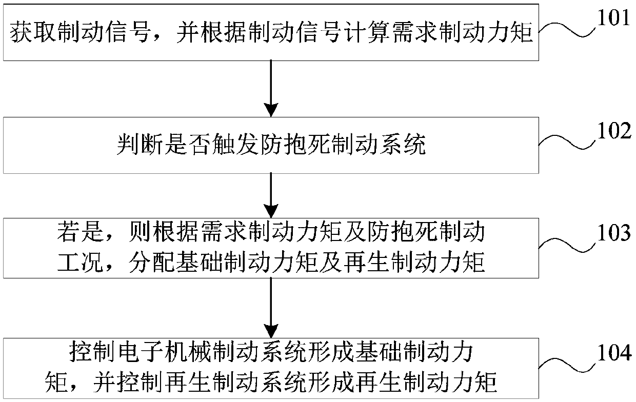
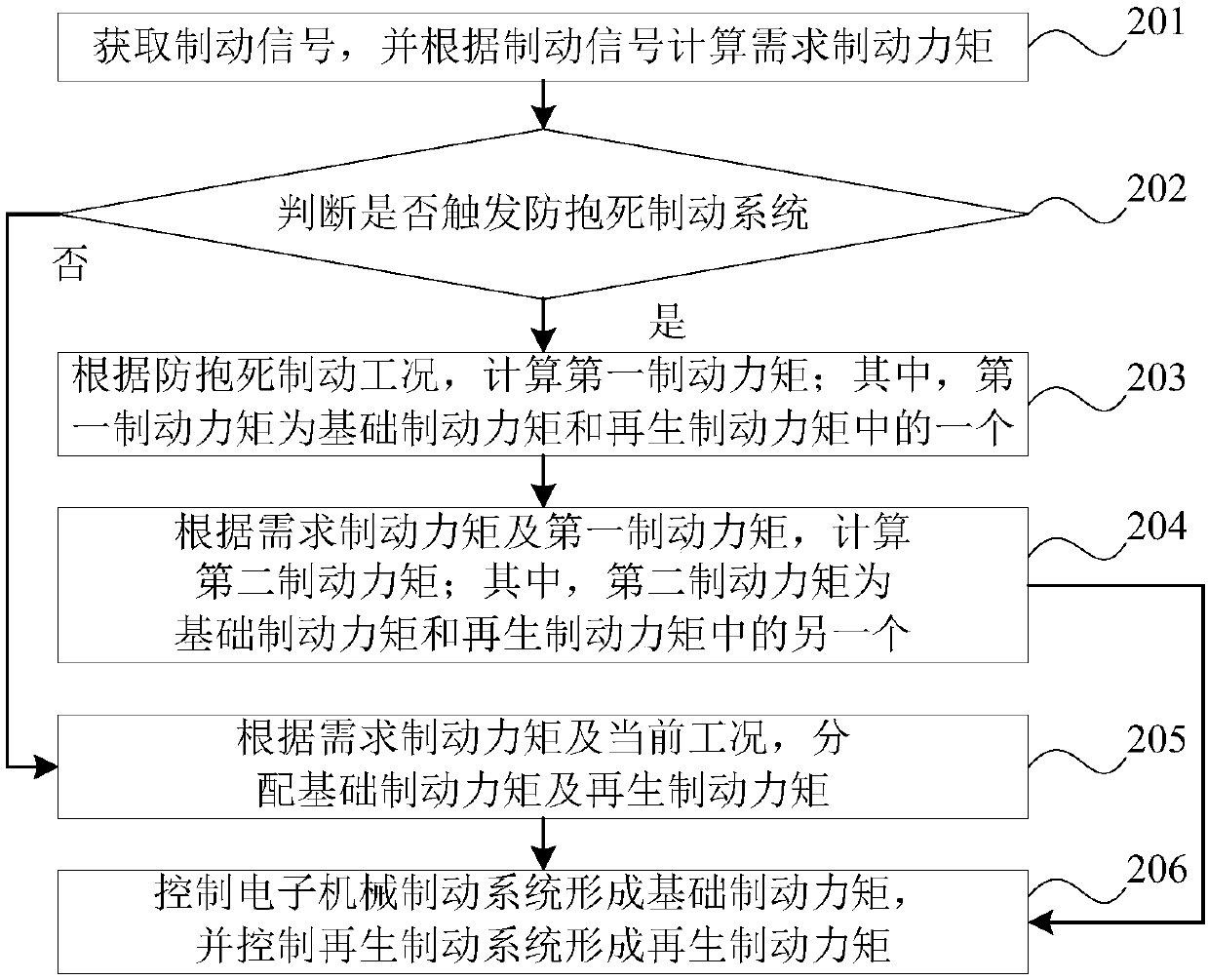
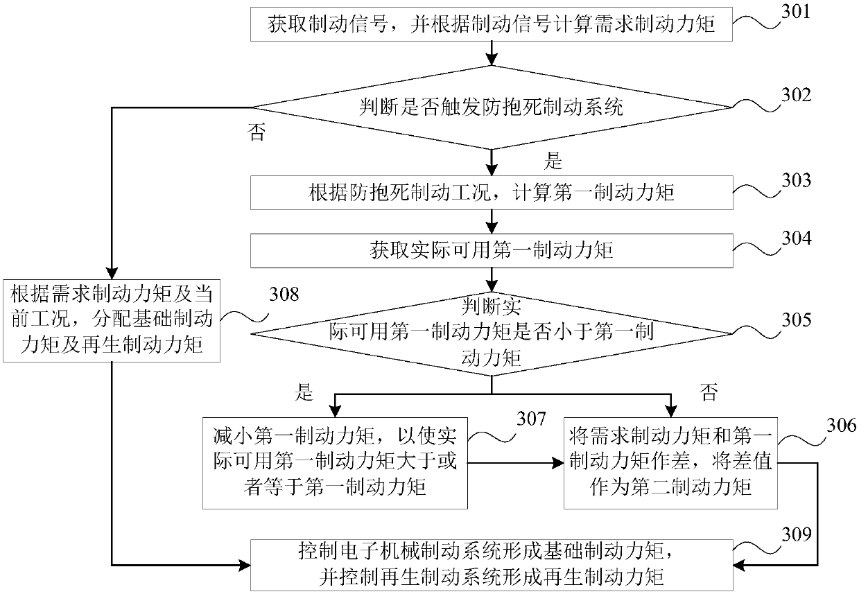
[0037] The control method and device of the compound braking system and the electric vehicle according to the embodiments of the present application will be described below with reference to the accompanying drawings. Before describing the embodiments of the present application in detail, for the sake of easy understanding, the commonly used t...


PUM


Abstract

The invention provides a control method and device of a composite braking system and an electric vehicle. The composite braking system comprises an electromechanical braking system and a regenerativebraking system, the electromechanical braking system is used for forming basic braking torque, the regenerative braking system is used for forming regenerative braking torque, and the control method comprises the steps that a braking signal is obtained, and the required braking torque is calculated according to the braking signal; judging whether an anti-lock braking system is triggered or not; ifyes, distributing a basic braking torque and a regenerative braking torque according to the required braking torque and the anti-lock braking working condition; and controlling the electromechanicalbraking system to form a basic braking torque, and controlling the regenerative braking system to form a regenerative braking torque. According to the method, the cooperative braking function of the regenerative braking system and the electromechanical braking system can be provided for the electric vehicle, the regenerative braking system is fully utilized to recover energy within the full working condition range of the electric vehicle, and the endurance mileage of the electric vehicle is increased.

Description

technical field [0001] The present application relates to the technical field of vehicle control, in particular to a control method and device for a composite braking system and an electric vehicle. Background technique [0002] As users continue to improve the braking performance of electric vehicles, anti-lock braking system (Anti-lock Braking System, referred to as ABS), traction control system (Traction Control System, referred to as TCS), electronic stability control program (Electronic Stability Program , ESP for short), adaptive cruise control system (Adaptive Cruise Control System, ACC for short) and other electronic control functions are gradually integrated into the braking system of electric vehicles. [0003] In the prior art, when the anti-lock braking system is triggered, braking is performed by an electromechanical brake. [0004] In this way, the regenerative braking characteristics of the power motor are not fully utilized, and energy cannot be effectively ...

Claims


Application Information

Patent Timeline
Patent Type & Authority Applications(China)
IPC IPC(8): B60W30/18
CPCB60W30/18109B60W30/18127
Inventor 吕海军廖银生
Owner BYD CO LTD
Why Eureka
Try Eureka