
Cleaning equipment applied to roads and bridges

A technology for cleaning equipment and bridges, applied in road cleaning, cleaning methods, construction, etc., can solve problems such as water on the road surface and affecting the cleaning efficiency of cleaning vehicles

Active Publication Date: 2020-06-26
苏州市相城区渭塘城乡发展有限公司
View PDF6 Cites 1 Cited by
  • Summary
  • Abstract
  • Description
  • Claims
  • Application Information

AI Technical Summary

Problems solved by technology

[0002] Nowadays, in order to beautify the environment, political and city appearance, people pay more and more attention to road surface cleaning projects. When cleaning the road surface, they usually use cleaning vehicles to clean up. The cleaning vehicles are usually equipped with induced draft fans, ventilation ducts and dust suction ports. A brush is usually installed at the dust suction port to clean the dust on the road surface. However, when the cleaning vehicle is moving forward when cleaning the road surface, it is often encountered that there is water on the road surface. The water will wet the brush and affect the cleaning of the cleaning vehicle. Efficiency, in addition, the existing pumping system cylinder is easy to suck small but hard objects in one pass, and an additional filter structure is required

Method used


Image

  • Cleaning equipment applied to roads and bridges
  • Cleaning equipment applied to roads and bridges
  • Cleaning equipment applied to roads and bridges

Examples


Embodiment Construction

[0019] The following will clearly and completely describe the technical solutions in the embodiments of the present invention with reference to the accompanying drawings in the embodiments of the present invention. Obviously, the described embodiments are only some, not all, embodiments of the present invention. Based on the embodiments of the present invention, all other embodiments obtained by persons of ordinary skill in the art without making creative efforts belong to the protection scope of the present invention.

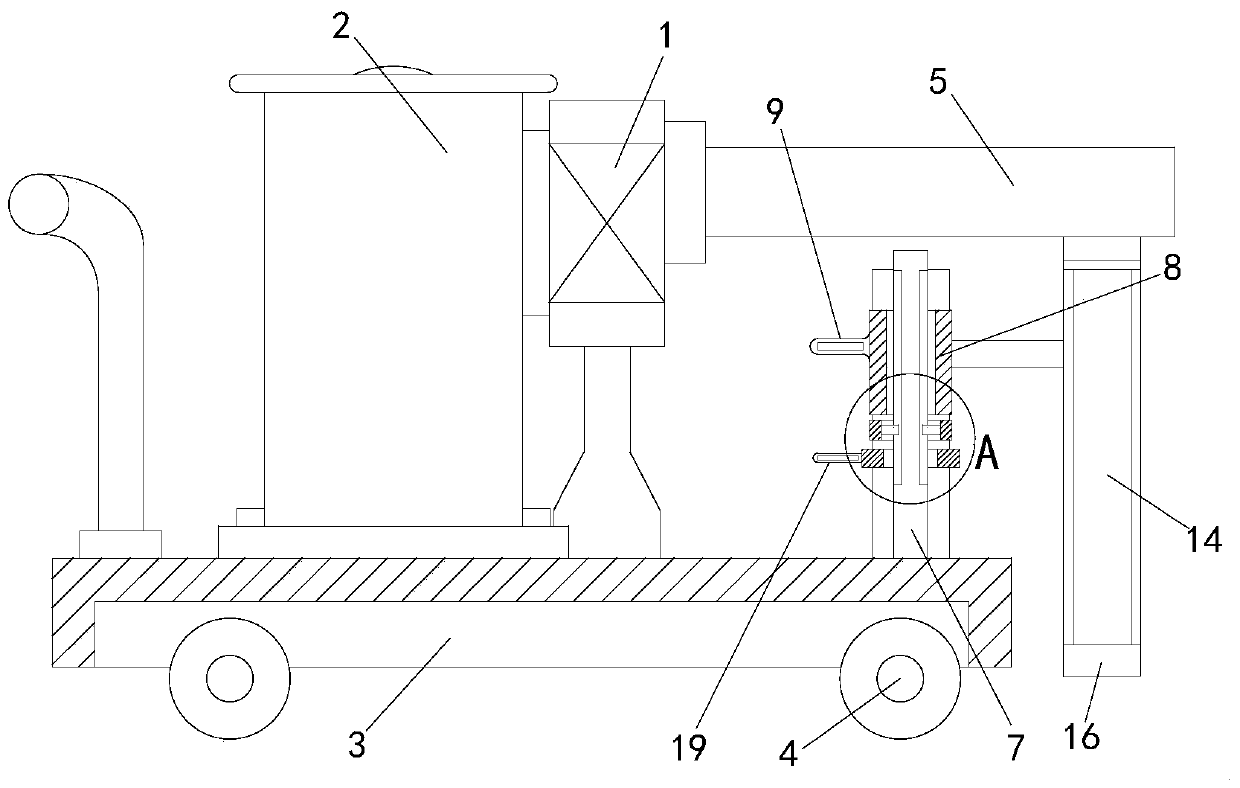
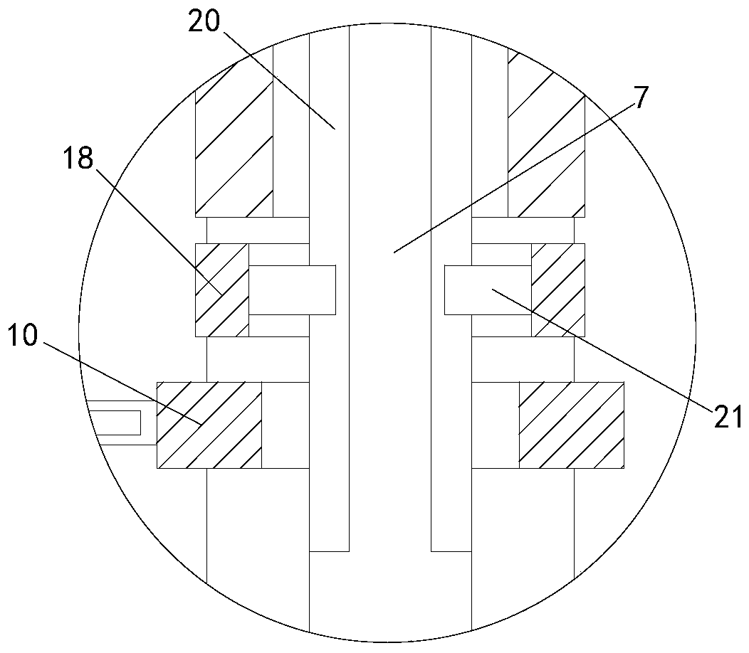
[0020] see Figure 1-4 , a cleaning device applied to roads and bridges of the present invention, comprising an induced draft fan 1, a dust collecting bucket 2, a support plate 3 and a rolling wheel 4, the dust collecting bucket 2 and the induced draft fan 1 are all arranged on the support The top of the plate 3, the scroll wheel 4 is arranged on the bottom of the support plate 3, the air inlet end of the induced draft fan 1 is provided with a ventilation duct...


PUM


Abstract

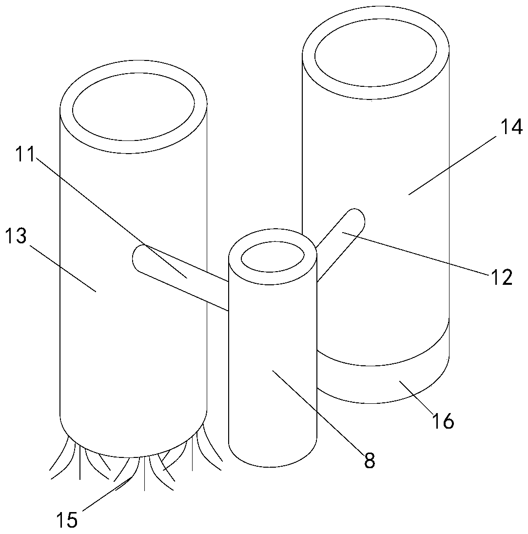
The invention discloses cleaning equipment applied to roads and bridges. The device comprises an induced draft fan, a dust collecting barrel, a supporting plate and rolling wheels, a ventilating pipeline is arranged at the air inlet end of the induced draft fan; a first connector is arranged at the tail end of the ventilating pipeline; a first supporting rod is arranged at the top of the front endof the supporting plate; the outer side of the first supporting rod is sleeved with a connecting sleeve; a first hollow connecting rod and a second hollow connecting rod are arranged on the outer side of the connecting sleeve; the axis of the first hollow connecting rod and the axis of the second hollow connecting rod are horizontally arranged and perpendicular to each other. A first cleaning cylinder is arranged at the end, away from the connecting sleeve, of the first hollow connecting rod. A second cleaning cylinder is arranged at the end, away from the connecting sleeve, of the second hollow connecting rod. A brush is arranged at the bottom of the first cleaning cylinder, a sealing ring is arranged at the bottom of the second cleaning cylinder, the sealing ring is made of soft rubber,the first rotating rod on the connecting sleeve is wrenched according to the front road condition, switching between the first cleaning cylinder and the second cleaning cylinder is achieved, and thesituation that the cleaning efficiency is affected due to the fact that the brush is wetted by water can be effectively avoided.

Description

technical field [0001] The invention relates to the technical field of road surface cleaning, in particular to a cleaning device applied to roads and bridges. Background technique [0002] Nowadays, in order to beautify the environment, political and city appearance, people pay more and more attention to road surface cleaning projects. When cleaning the road surface, they usually use cleaning vehicles to clean up. The cleaning vehicles are usually equipped with induced draft fans, ventilation ducts and dust suction ports. A brush is usually installed at the dust suction port to clean the dust on the road surface. However, when the cleaning vehicle is moving forward when cleaning the road surface, it is often encountered that there is water on the road surface. The water will wet the brush and affect the cleaning of the cleaning vehicle. In addition, it is easy to inhale smaller but harder objects in the cylinder of the existing pumping system, and an additional filter struct...

Claims


Application Information

Patent Timeline
Patent Type & Authority Applications(China)
IPC IPC(8): E01H1/08
CPCE01H1/0845
Inventor 房蕊李华昌李文静刘胜文
Owner 苏州市相城区渭塘城乡发展有限公司
Learn More