A continuous river sewage collection and cleaning system

A continuous type of dirt collection technology, which is applied in the cleaning of open water surfaces, construction, water conservancy projects, etc., can solve the problems of poor flow rate and increase the pressure of pressure-bearing equipment on both sides, so as to prevent deformation and improve load-bearing capacity Effect

Active Publication Date: 2021-08-06
SHANDONG WATER GENERAL CO LTD
View PDF6 Cites 0 Cited by
  • Summary
  • Abstract
  • Description
  • Claims
  • Application Information

AI Technical Summary

Problems solved by technology

[0004] The purpose of the present invention is to provide a continuous river sewage collection and cleaning system to solve the main problem of whether the river flow can flow normally when the river flow is large and the water level rises high. If it is stuck and no longer rises, the rise of the water level will increase the pressure of the pressure-bearing equipment on both sides, resulting in a technical problem of poor flow rate.

Method used


Image

  • A continuous river sewage collection and cleaning system
  • A continuous river sewage collection and cleaning system
  • A continuous river sewage collection and cleaning system

Examples


Embodiment 1

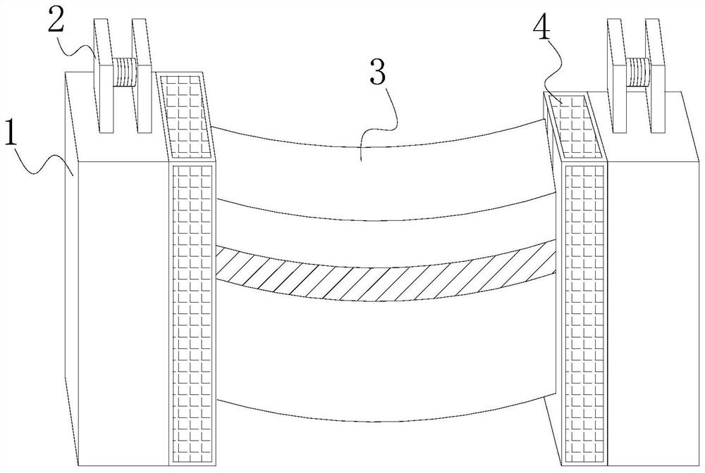
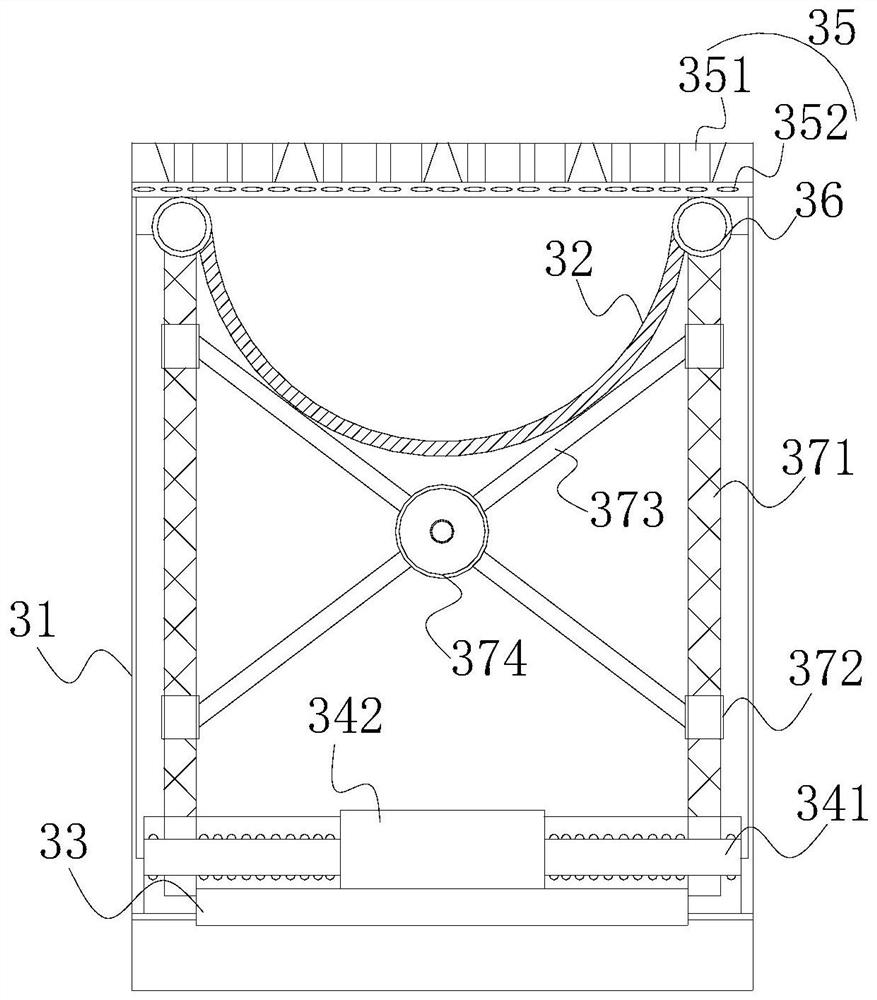
[0029] Such as Figure 1-Figure 3 As shown, the present invention provides a continuous riverway sewage collection and cleaning system, the structure of which includes a load-bearing platform 1, a hoist 2, a dirt-stopping plate 3, and a dirt-collecting tank 4. The hoist 2 of the plate 3, the connection between the dirt-blocking plate 3 and the dirt-collecting tank 4 is slidingly fitted, and the side matching position of the dirt-blocking plate 3 and the dirt-collecting tank 4 is provided with a chute. The dirt block 3 is a cavity type, and its top is not closed. The dirt block 3 is composed of a block body 31, a bearing liner 32, a support base 33, a lifting control center 34, an impact detection module 35, an installation port 36, An inner tank movable mechanism 37, the two ends of the bearing inner tank 32 are fixed inside the dirt block frame 31 through the installation opening 36, the impact detection module 35 is located at the upper end of the bearing inner tank 32, and ...

Embodiment 2

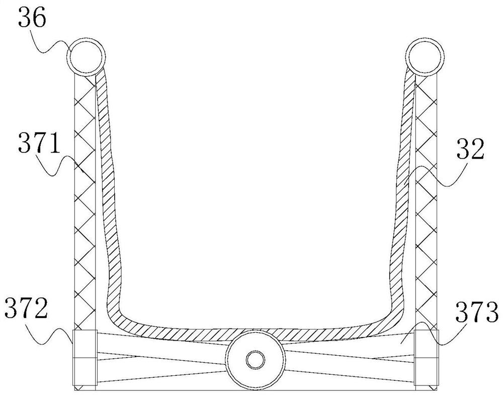
[0032] Such as Figure 4-Figure 5As shown, based on Embodiment 1 to achieve better water flow when the water level rises and falls and the trash catch plate can work normally, combined with the mutual cooperation of the following structural components, the shear rod 373 includes a telescopic sub-rod 731, a telescopic mother rod 732, a card slot 733, an interface 734, a block 735, and a counterweight assembly 736. The telescopic sub-rod 731 runs through the inside of the telescopic mother rod 732, and the two are telescopically matched in a horizontal straight line. There is an interface 734, on both sides of the interface 734 there are clamping blocks 735, on the inner surface wall of the telescopic female rod 732 there is a clamping groove 733 engaged with the clamping block 735, and the clamping grooves 733 are symmetrically distributed, symmetrical There are two on one side, and a counterweight assembly 736 is provided between the interfaces 734. The interface 734 is a cavi...


PUM


Abstract

The invention discloses a continuous river channel sewage collection and cleaning system, the structure of which includes a load-bearing platform, a hoist, a sewage catcher, and a sewage collection tank. The dirt collection tanks are connected by a sliding fit. There is a chute at the matching position between the dirt catcher plate and the side of the dirt collection tank. The dirt catcher plate is hollow and its top is not closed. The dirt catcher plate is composed of a dirt catcher frame , carrying liner, support base, lifting control center, impact detection module, installation port, liner movable mechanism, the trash plate of the present invention is made into a structure that the top of the cavity is not closed, and the load-carrying liner acts on the inside of the trash block outer frame , when the water level rises higher and overflows the trash baffle, the water will flow into the load-bearing liner to increase the weight of the trash baffle, and when the gravity is greater than the buoyancy, the trash baffle will sink, so as to better realize the flow and reduce the two side pressure.

Description

technical field [0001] The invention relates to the field of water conservancy facilities, in particular to a continuous river channel sewage collection and cleaning system. Background technique [0002] Our country has many mountains and rivers, and the distribution of water resources is uneven. Therefore, it is necessary to build many water conservancy projects. While scientifically regulating water resources, water resources are used to generate electricity. Its role is often to prevent the floating objects in the water from entering the internal structure of the water conservancy project and affecting the normal operation of the water conservancy project. Therefore, the quality of the pollution blocking effect can play a very critical role in the normal operation of the water conservancy project. [0003] Cleaning of floating objects in water conservancy rivers is a device that comprehensively utilizes the buoyancy, impact force and other properties of water to automatic...

Claims


Application Information

Patent Timeline
Patent Type & Authority Patents(China)
IPC IPC(8): E02B15/10
CPCE02B15/10
Inventor 郑素花
Owner SHANDONG WATER GENERAL CO LTD
Why Eureka
Try Eureka