Light-transmitting cover plate and optical device
A light-transmitting cover and cover technology, applied in the optical field, can solve the problems of high price, expensive light source modules, and large light loss, and achieve the effects of improving light efficiency, reducing costs, and reducing power consumption of the whole machine
- Summary
- Abstract
- Description
- Claims
- Application Information
AI Technical Summary
Problems solved by technology
Method used
Image

Examples
Example Embodiment
[0038] Example 1
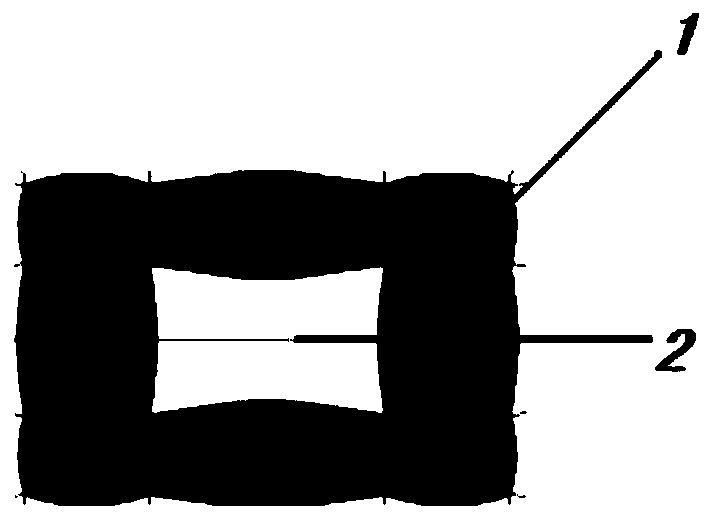
[0039] Such as figure 2 As shown, in this embodiment, the micro lens unit adopts an implementation manner in which the micro lens unit is arranged in a one-dimensional plane. In order to form a rectangular light spot, the shape of the micro lens unit is roughly rectangular.
[0040] The micro lens unit of this embodiment includes: a first micro lens 1 and a second micro lens 2.
[0041] Wherein, the first microlens 1 is distributed on the peripheral side of the second microlens 2, that is, the first microlens 1 is continuously arranged around the second microlens 2 described above. The edge of the first microlens 1 and the edge of the second microlens 2 are smoothly connected. Since the shape of the microlens unit of this embodiment is roughly rectangular, the first microlens 1 located on the peripheral side of the second microlens 2 is correspondingly arranged in a rectangular ring structure.
[0042] The above-mentioned first microlens 1 of the rectangular ring...
Example Embodiment
[0045] Example 2
[0046] In this embodiment, the micro lens unit adopts an implementation manner in which the micro lens unit is arranged in a one-dimensional plane. In order to form a pentagonal light spot, the shape of the micro lens unit is roughly a pentagon.
[0047] The micro lens unit of this embodiment includes: a first micro lens and a second micro lens.
[0048] Wherein, the first microlens is distributed on the peripheral side of the second microlens, that is, the first microlens is continuously arranged around the second microlens. The edge of the first microlens and the edge of the second microlens are smoothly connected. Since the shape of the micro lens unit of this embodiment is approximately a pentagon, the first micro lens located on the peripheral side of the second micro lens is correspondingly arranged in a pentagon ring structure.
[0049] The first microlens of the above-mentioned pentagonal ring structure includes a plurality of arcuate curved surfaces, and ...
Example Embodiment
[0051] Example 3
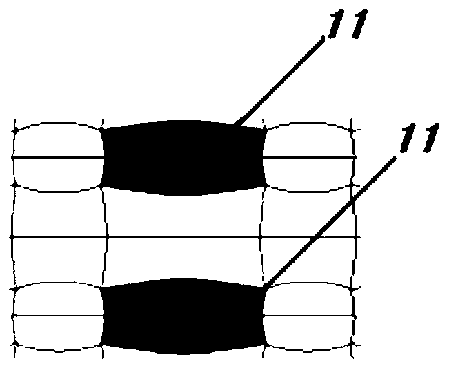
[0052] Such as Image 6 As shown, in this embodiment, the micro lens unit adopts an implementation manner in which the micro lens unit is spatially arranged in planes of different dimensions. Specifically, it is an embodiment in which a plurality of micro lens units are respectively distributed in different spatial dimensions. In order to form a rectangular light spot, the shape of any microlens unit is roughly rectangular.
[0053] The micro lens unit of this embodiment includes: a first micro lens 1 and a second micro lens 2. Wherein, the first microlens 1 is distributed at a local position on the peripheral side of the second microlens 2, and the edge of the first microlens 1 and the edge of the second microlens 2 are smoothly connected.
[0054] In one embodiment, there are two microlens units in this embodiment, and the two microlens units are arranged in a layered manner. The layered arrangement referred to here includes: two microlens units close to each o...
PUM
 Abstract
Description
Claims
Application Information
 - R&D Engineer
- R&D Manager
- IP Professional
- Industry Leading Data Capabilities
- Powerful AI technology
- Patent DNA Extraction
Browse by: Latest US Patents, China's latest patents, Technical Efficacy Thesaurus, Application Domain, Technology Topic.
© 2024 PatSnap. All rights reserved.Legal|Privacy policy|Modern Slavery Act Transparency Statement|Sitemap