
Electric push rod type annular battery device with self-replacement function

A battery device and push rod type technology, which is applied in the direction of secondary batteries, secondary battery testing, battery pack components, etc., can solve the problems of difficult detection, replacement, maintenance efficiency, etc., and achieve reasonable and reliable structural design, stable structure, and accuracy The effect of rate guarantee

Active Publication Date: 2020-06-26
ZAOZHUANG UNIV
View PDF5 Cites 2 Cited by
  • Summary
  • Abstract
  • Description
  • Claims
  • Application Information

AI Technical Summary

Problems solved by technology

[0004] The present invention provides an electric push rod type annular battery device with a self-replacement function in order to solve the problem that existing annular battery packs are difficult to detect and replace during use and affect maintenance efficiency.

Method used


Image

  • Electric push rod type annular battery device with self-replacement function
  • Electric push rod type annular battery device with self-replacement function

Examples


Embodiment Construction

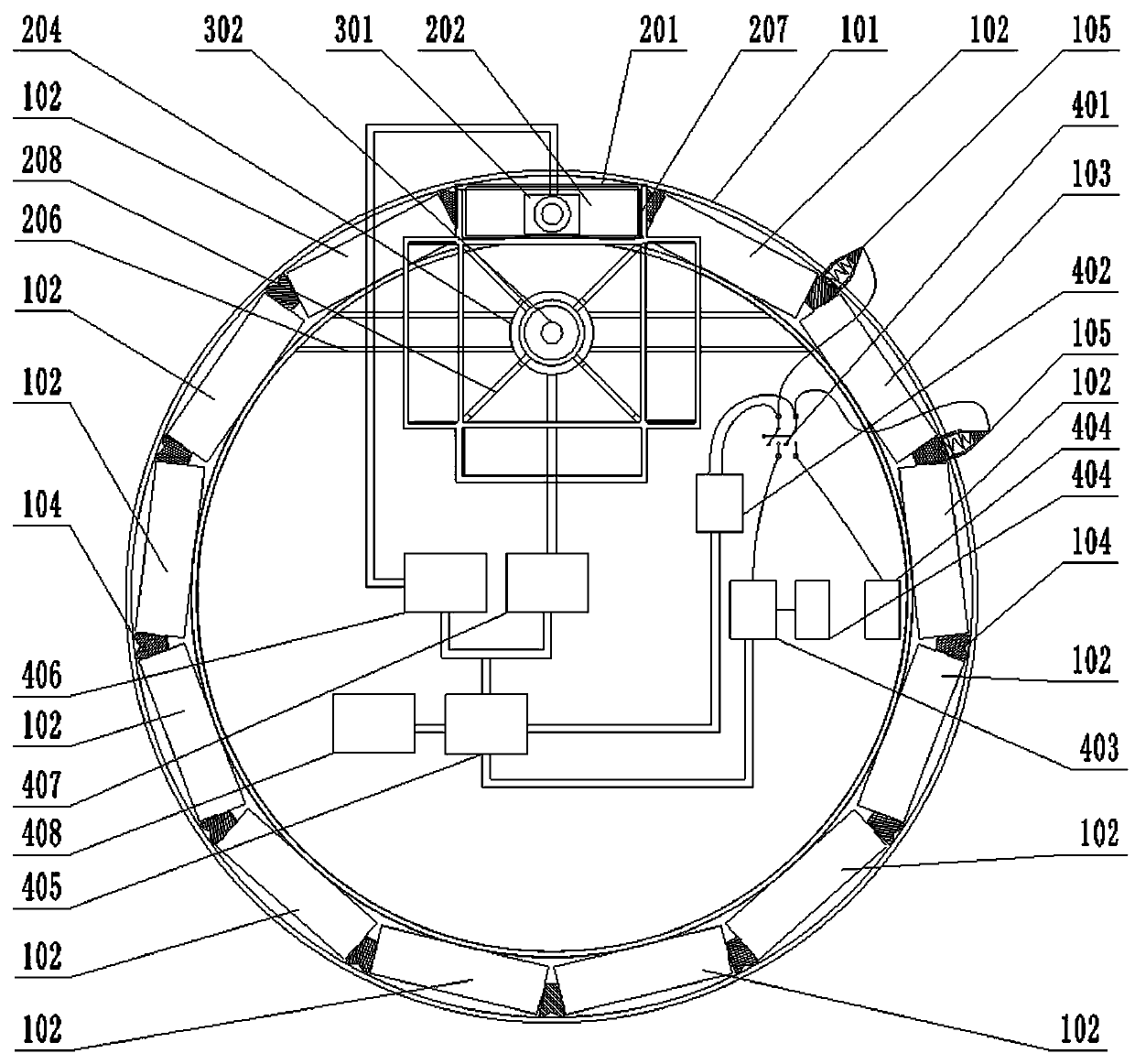
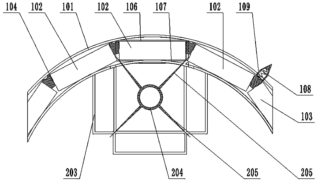
[0030] An electric push rod type annular battery device with self-replacement function, comprising a main body, a driving portion and a control portion; the main body includes an annular battery pack and a battery replacement rack;

[0031]The annular battery pack includes a circular track groove 101 with the notch facing upwards, and the inner chamber of the circular track groove 101 is provided with twelve working batteries 102, an insulating column 103 and thirteen working batteries 102 in the same size as the working battery 102. A connection terminal 104 interleaved with the working battery 102 and the insulating column 103; two adjacent working batteries 102 are connected in series through the connecting terminal 104 between the two, and there is an operating line between the two adjacent working batteries 102 gap; the outer wall of the circular track groove 101 is provided with two fixed contacts 105, and the two fixed contacts 105 are respectively electrically connected...


PUM


Abstract

The invention particularly relates to an electric push rod type annular battery device with a self-replacement function, and solves the problem that the maintenance efficiency is influenced due to thefact that an existing annular battery pack is difficult to detect and replace during use. According to the invention, a working battery and an insulating column are arranged in an inner cavity of anannular rail groove, a fixed contact is arranged outside the annular rail groove, a battery falling hole is formed below one working battery, and an arc-shaped operation window hole is formed in the inner side of one working battery; a rotary supporting cylinder is fixedly connected between the standby battery storage rack and the damaged battery storage rack, and a radial poking claw is arrangedon the outer side wall of the rotary supporting cylinder in an extending mode and extends into the operation gap; the push rod direction of the electric push rod is downward; an output shaft of the stepping motor is fixedly arranged in the rotary supporting cylinder in a penetrating mode; and the control part comprises a micro-control unit. According to the invention, automatic detection and replacement of the damaged battery are realized, and the maintenance efficiency is greatly improved.

Description

technical field [0001] The invention relates to battery replacement technology, in particular to an electric push rod type annular battery device with self-replacement function. Background technique [0002] With the development of modern technology, traditional square or cylindrical lithium batteries are difficult to meet the needs of some special-shaped electronic products with ring or circular structures. Connecting lithium batteries in series or in parallel to form a ring-shaped battery pack can not only ensure its capacity and use safety, but also better match the ring structure or circular structure of electronic products. [0003] However, practice has shown that the existing ring-shaped battery packs have the following problems in use: one is that each battery in the ring-shaped battery pack is connected in parallel or in series, and individual battery damage will directly affect the use of the entire ring-shaped battery pack. Each battery unit in the battery pack i...

Claims


Application Information

Patent Timeline
Patent Type & Authority Applications(China)
IPC IPC(8): H01M2/10H01M10/42H01M10/48
CPCH01M10/425H01M10/4285H01M10/48H01M50/20Y02E60/10
Inventor 殷帅于春蕾田婷史洋张义生包赢超孙斐斐徐伟卢纪丽李帅李辉张业伟孙正杨青运孙振川
Owner ZAOZHUANG UNIV
Learn More