Folding and unfolding structure and method of log-periodic antenna

A logarithmic periodic antenna, antenna technology, applied in antennas, folded antennas, antenna arrays, etc., can solve problems such as transportation difficulties, excessive length of the vibrator, and reducing the occupied area.

Pending Publication Date: 2020-06-26
SHENZHEN WAVE TELECOMM TECH CO LTD
View PDF0 Cites 0 Cited by
  • Summary
  • Abstract
  • Description
  • Claims
  • Application Information

AI Technical Summary

Problems solved by technology

[0003] Based on this, it is necessary to address the above problems and provide a log-periodic antenna retractable structure, which can fold the log-periodic antenna array, reduce its occupied area, and solve the problem of transportation difficulties caused by the long length of the vibrator

Method used


Image

  • Folding and unfolding structure and method of log-periodic antenna
  • Folding and unfolding structure and method of log-periodic antenna
  • Folding and unfolding structure and method of log-periodic antenna

Examples


Embodiment 1

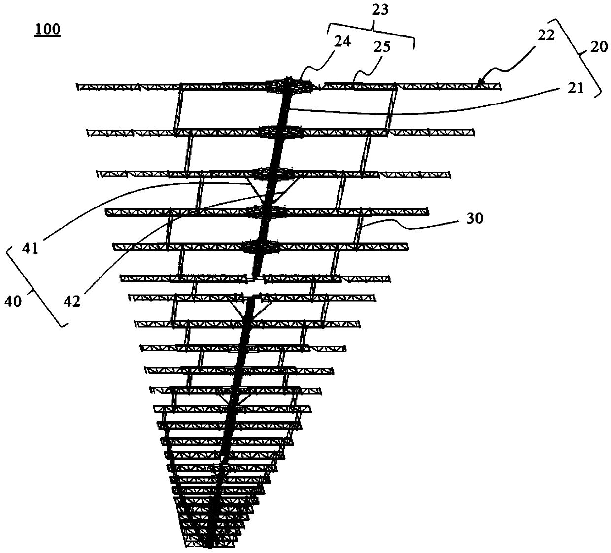
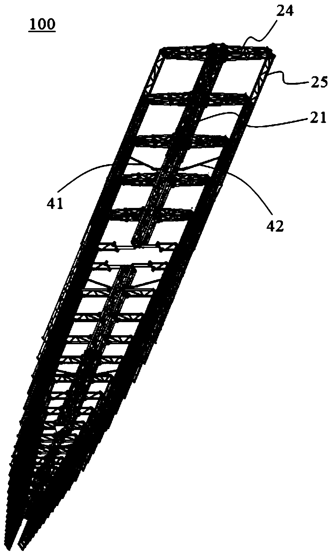
[0033] Such as figure 1 and figure 2 As shown, the deployment structure 100 of the log-periodic antenna in this embodiment includes a log-periodic antenna array 20, a number of first connectors 30 installed on the log-periodic antenna array 20, and a first antenna deployment device 40, which can The logarithmic periodic antenna array 20 is automatically folded to reduce its occupied area and solve the problem of transportation difficulties caused by the excessively long length of the vibrator.

[0034] Such as figure 1 As shown, the logarithmic periodic antenna array 20 includes a truss 21 and a multi-layer first antenna 22 installed on the truss 21, each layer of the first antenna 22 includes a pair of first oscillators 23, and a pair of first oscillators 23 are respectively connected to On both sides of the truss 21 , the first vibrator 23 includes a first fixed section 24 and a first movable section 25 movably connected to the first fixed section 24 , and one end of the ...

Embodiment 2

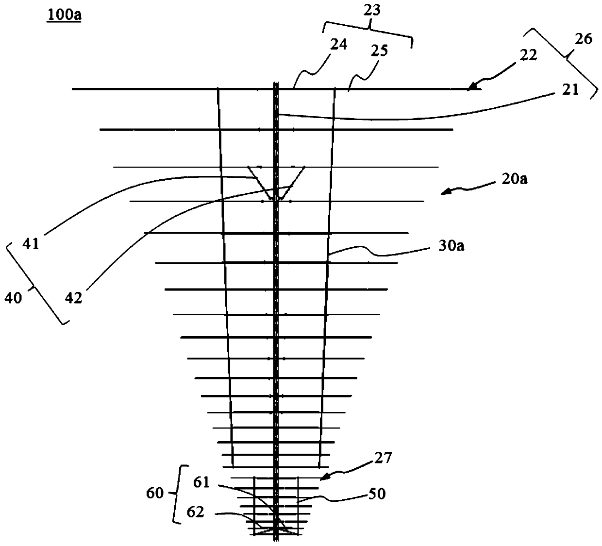
[0052] Such as image 3 and Figure 4 As shown, the differences between the expanded structure 100a of the log-periodic antenna in this embodiment and the expanded structure 100 of the log-periodic antenna in Embodiment 1 are:

[0053] All the first antennas 22 are connected to the truss 21 to form the first array 26. The log-periodic antenna array 20a also includes a second array 27 installed on the truss 21. The second array 27 includes a multi-layer second antenna (not marked), each The second layer antenna includes a pair of second oscillators 210, and the pair of second oscillators 210 are respectively connected to both sides of the truss 21. The second oscillator 210 includes a second fixed section 28 and a second movable section movably connected to the second fixed section 28. Section 29, the second fixed section 28 is connected to the truss 21 at one end away from the second movable section 29; the first array 26 and the second array 27 are installed on the truss 21 ...


PUM


Abstract

The invention relates to a folding and unfolding structure and method of a log-periodic antenna. The folding and unfolding structure comprises a log-periodic antenna array, and the log-periodic antenna array comprises a truss, a plurality of layers of first antennas arranged on the truss, a plurality of first connecting pieces and a first antenna folding and unfolding device, wherein each layer offirst antenna comprises a pair of first oscillators, the pair of first oscillators are connected to the two sides of the truss respectively, each first oscillator comprises a first fixed section anda first movable section movably connected with the first fixed section, and the end, away from the first movable section, of the first fixed section is connected with the truss; two ends of each firstconnecting piece are respectively connected with the first movable sections of two adjacent first oscillators in the extending direction of the truss; the first antenna folding and unfolding device is installed on the truss and connected with the first movable sections on the two sides of the truss, and the first antenna folding and unfolding device is used for unfolding and folding the first antenna. And the log-periodic antenna array can be folded, so the occupied area is reduced, and the problem of transportation difficulty caused by overlong oscillators is solved.

Description

technical field [0001] The invention relates to the technical field of communication equipment, in particular to a deployment structure and a deployment method of a logarithmic periodic antenna. Background technique [0002] Due to the characteristics of long propagation distance, low cost and strong anti-interference ability, coupled with the ease of operation and flexibility of the equipment, the short-wave antenna has an irreplaceable unique position in the field of military and civilian communications. Among them, the short-wave antenna in the short-wave antenna is widely used due to the advantages of wide frequency bandwidth and good directivity. However, when the transmission frequency of the short-wave antenna is required to be 3-30Mhz, the corresponding logarithmic period antenna oscillator length is about 25m, that is, the use of 3 wires The structural form of the antenna is also about 15 meters in length, which is a big challenge for the current vehicle-mounted tra...

Claims


Application Information

Patent Timeline
IPC IPC(8): H01Q1/08H01Q1/12H01Q1/36H01Q21/00
CPCH01Q1/084H01Q1/12H01Q1/36H01Q21/00
Inventor 刘海涛张少林
Owner SHENZHEN WAVE TELECOMM TECH CO LTD
Why Eureka
Try Eureka