Field mounting method for test chamber

A technology of on-site installation and test cabin, applied in auxiliary devices, auxiliary welding equipment, welding/cutting auxiliary equipment, etc., can solve the problem of difficult installation of test cabins

Inactive Publication Date: 2015-12-23
SHENYANG AEROSPACE XINGUANG PRESSURE VESSEL
View PDF5 Cites 5 Cited by
  • Summary
  • Abstract
  • Description
  • Claims
  • Application Information

AI Technical Summary

Problems solved by technology

[0003] Aiming at the problems existing in the above-mentioned prior art, the present invention provides an on-site installation method of the test cabin, which solves the problem of difficulty in the on-site installation of the test cabin in the prior art

Method used

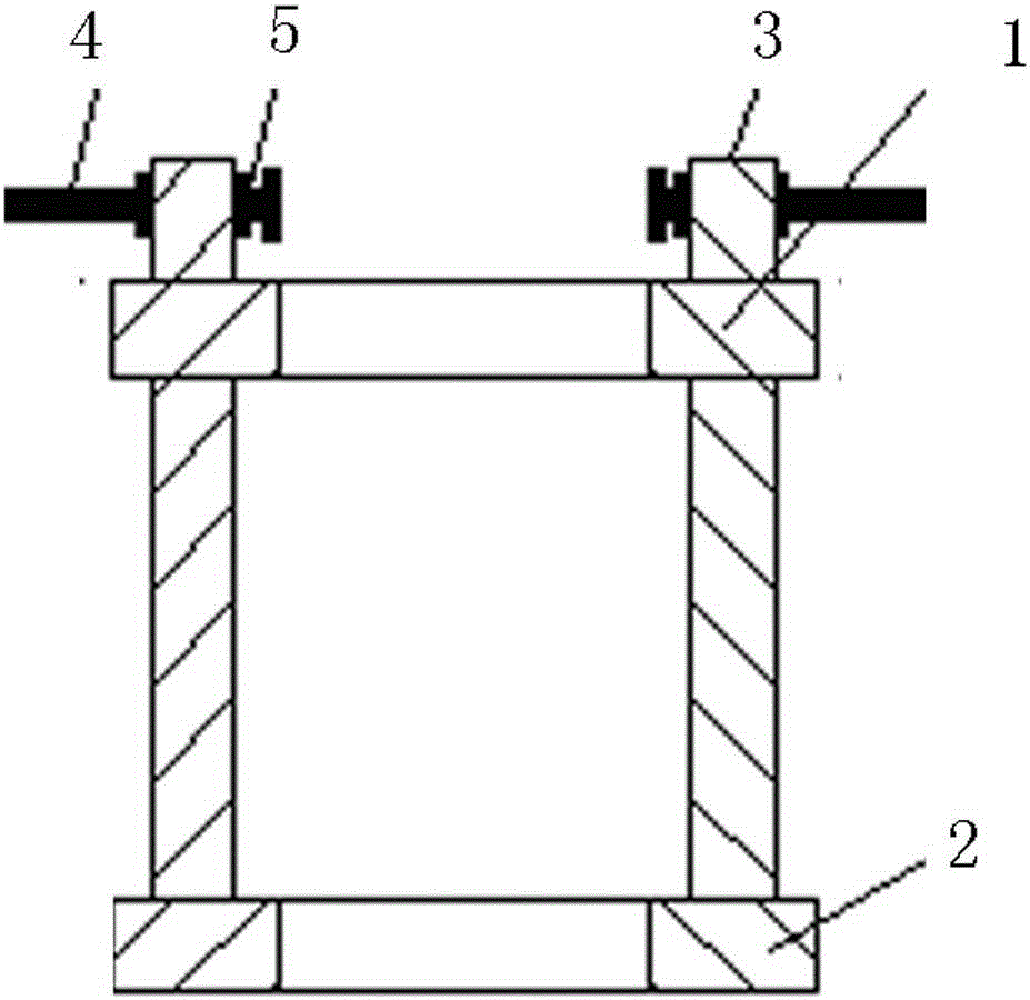
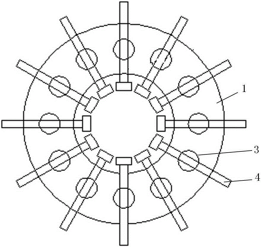
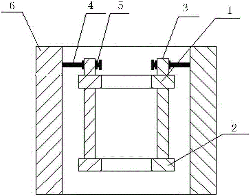

Image

  • Field mounting method for test chamber
  • Field mounting method for test chamber
  • Field mounting method for test chamber

Examples


Embodiment

[0032] Taking the 8000mm inner diameter of the barrel section cylinder as an example, the installation method of the present invention includes the following steps:

[0033] Step 1 Picking materials: pick up the material Q345R, δ=52mm plate, the surface of the material should not have defects such as cracks, delamination, folding, and slag inclusions; the surface defects of the plate are allowed to be removed and ground, and the ground part should be smoothly transitioned;

[0034] Step 2 blanking: cutting the above-mentioned sheet by gas cutting, removing the surface slag and oxides generated during gas cutting and cutting, and grinding the periphery to be smooth, without cracks or slag inclusions on the end surface;

[0035] Step 3 Edge planing: the surface of the groove of the above-mentioned sheet shall have no defects, and the roughness shall not be lower than 25;

[0036] Step 4 Welding panel: the above-mentioned panels are laid out according to the process, and the pane...


PUM

PropertyMeasurementUnit
thicknessaaaaaaaaaa
diameteraaaaaaaaaa

Abstract

The invention relates to a field mounting method for a test chamber. The field mounting method comprises the following steps: requiring boards; blanking the boards; carrying out edge planning on the boards; welding and joining the boards; rolling the boards into a winding drum; longitudinally welding the winding drum to form drum sections; carrying out roundness correction on the drum sections; carrying out gas cutting on the drum sections; fitting up and welding the drum sections; cutting the drum sections into parts; carrying out field welding on the parts; and carrying assembly welding on an enclosure and the drum sections. The field mounting method solves the problem that a large container is difficult to transport, guarantees the field mounting coaxiality, adopts split transportation and field welding, utilizes a tool to support welding, and guarantees that the roundness of a drum body reaches standard requirements.

Description

technical field [0001] The invention relates to an installation method of a large container, in particular to an on-site installation method of a test cabin. Background technique [0002] The overall shape of the test cabin is a cylinder, which mainly includes: the body of the test cabin, the door of the test cabin, the integrated feeding car and its moving track, etc. The internal size of the test chamber is φ8mx12m. The installation process of this large container is relatively complicated, and it is installed on site, which will encounter many problems. For example, it is difficult to ensure the coaxiality of large containers on site, and the welding deformation is large, and ring welding is easy to occur. The seam is not connected or the amount of misalignment and edge angle exceed the range required by the standard; and transportation is inconvenient. Contents of the invention [0003] Aiming at the problems existing in the above-mentioned prior art, the present inve...

Claims


Application Information

Patent Timeline
Patent Type & Authority Applications(China)
IPC IPC(8): B23P15/00B23K37/00
CPCB23K37/00B23P15/00
Inventor 刘为
Owner SHENYANG AEROSPACE XINGUANG PRESSURE VESSEL
Why Eureka
Try Eureka