Gas meter system

一种燃气表、燃气的技术,应用在信号传输系统、电气元件、传输电表数据等方向,能够解决作业人员无法适当地进行判断、异常消除方法复杂等问题

Active Publication Date: 2020-06-26
PANASONIC INTPROP MANAGEMENT CO LTD
View PDF10 Cites 0 Cited by
  • Summary
  • Abstract
  • Description
  • Claims
  • Application Information

AI Technical Summary

Problems solved by technology

In particular, in gas meters in recent years, as the number of functions of the meter has increased and its functions have become more advanced, there has been a problem that the "cause of abnormality" and "method of resolving the abnormality" for alarms or shutdowns that have occurred have changed. Complicated, workers cannot judge appropriately

Method used


Image

  • Gas meter system
  • Gas meter system
  • Gas meter system

Examples


no. 1 approach

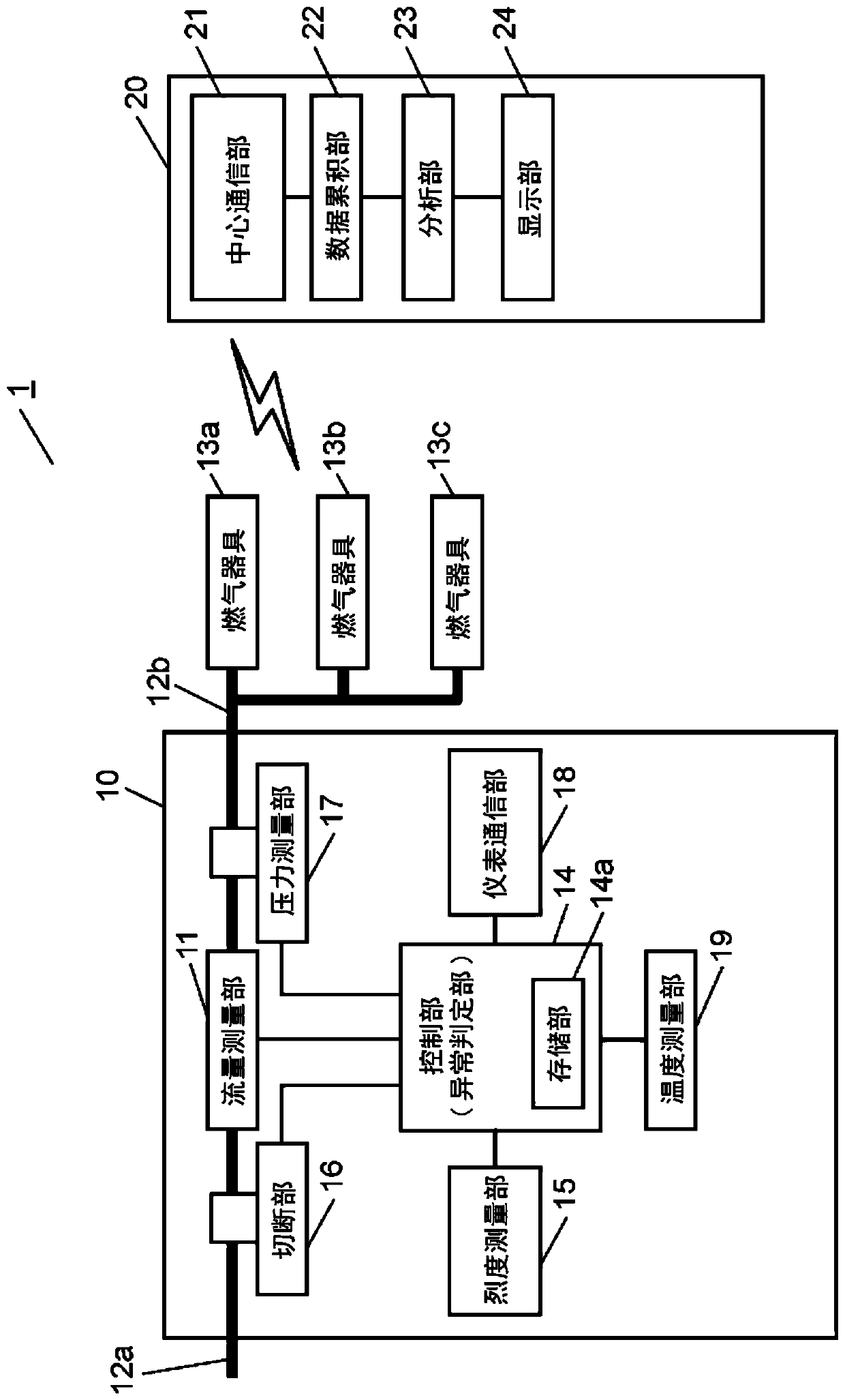
[0016] figure 1 It is a block diagram of the gas meter system in 1st Embodiment of this invention.

[0017] exist figure 1 Among them, the gas meter system 1 includes a central device 20 and a gas meter 10 installed in a user's house. In addition, although the gas meter 10 is installed in each user's house and exists in multiple numbers, only one gas meter 10 is described and demonstrated in this embodiment.

[0018] The gas meter 10 has a gas inflow pipe 12a and an outflow pipe 12b, and a flow measurement unit 11 is provided on a path from the inflow pipe 12a to the outflow pipe 12b. In addition, a plurality of gas appliances 13a, 13b, and 13c are connected downstream of the outflow pipe 12b.

[0019] The flow measurement unit 11 detects and outputs the flow of gas, and measures the instantaneous flow at predetermined intervals (for example, every 0.5 seconds).

[0020] The control unit 14 integrates the gas usage based on the flow rate data measured by the flow rate me...

no. 2 approach

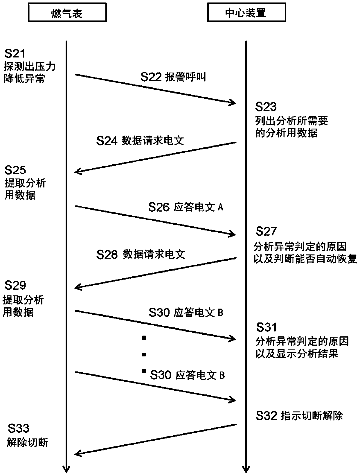
[0037] Next, use image 3 The operation of the gas meter 10 and the center device 20 of the gas meter system in the second embodiment will be described with reference to the communication sequence shown. In addition, the structure of the gas meter 10 and the central device 20 is the same as figure 1 The gas meter system in the first embodiment shown is the same, and description thereof will be omitted.

[0038] First, in step S21 , the abnormality determination unit of the control unit 14 determines that the pressure detected by the pressure measurement unit 17 is equal to or less than a preset predetermined value, and outputs abnormality type data that the pressure drop is abnormal. Next, in step S22 , a message (warning call) indicating a pressure drop abnormality is transmitted from the gas meter 10 to the center device 20 via the meter communication unit 18 as abnormality type data.

[0039] Next, in step S23, the central device 20 receives the telegram including the ab...


PUM


Abstract

The present invention comprises a gas meter (10), and a centre device (20) equipped with an analysis unit (23) that analyses the cause of an abnormality determination. On the basis of data by abnormality received from the gas meter (10), the centre device (20) sends a request to the gas meter (10), via communication by a centre communication unit (21), for analysis data required for analysing thecause of the abnormality determination. The gas meter (10) transmits the analysis data requested by the centre device (20) to the centre device (20) via a meter communication unit (18), and the analysis unit (23) of the centre device (20) identifies the cause of the abnormality detection on the basis of the received analysis data.

Description

technical field [0001] The present invention relates to a gas meter system including a gas meter having a gas shutoff function and a function of transmitting a shutoff reason when the shutoff is performed, and a center device for analyzing the shutoff cause. Background technique [0002] Conventionally, as such a gas meter system, there is an automatic notification device (for example, refer to Patent Document 1), which is connected to a meter (meter) that outputs cutoff reason data corresponding to the cutoff reason when the gas is cut off, and based on the cutoff reason, there is an automatic notification device. The reason data is automatically notified to the central device, and in the automatic notification device, the summary reason display means, in the case of outputting the cutoff reason data, shows the summary reason of the cutoff reason corresponding to the cutoff reason data; and displays the cutoff reason detailed reasons. [0003] Furthermore, according to the...

Claims


Application Information

Patent Timeline
Patent Type & Authority Applications(China)
IPC IPC(8): G01F3/22G01F1/00G01F15/06G08C15/00H04Q9/00
CPCH04Q9/00G01F15/063G01F15/005G01D4/004H04Q2209/60G01F1/34G01F15/002G01F15/003
Inventor 盐田和希白泽忠德村林信明田村吉邦
Owner PANASONIC INTPROP MANAGEMENT CO LTD
Why Eureka
Try Eureka