Calibration method for rapidly determining geometric position of each part in deflection measurement system

A technology of measurement system and calibration method, which is applied in the field of optical engineering and can solve problems such as the inability to directly determine the position of a workpiece

Active Publication Date: 2020-07-03
FUDAN UNIV
View PDF5 Cites 5 Cited by
  • Summary
  • Abstract
  • Description
  • Claims
  • Application Information

AI Technical Summary

Problems solved by technology

[0005] Aiming at the deficiencies of the prior art, the present invention provides a calibration method for quickly determining the geometric position of each component in the deflection measurement system, which has the advantages of being simple and fast, and solves the problem that the position of the workpiece cannot be directly determined and the inherent problems of deflection measurement cannot be solved. "Height-slope ambiguity", a problem that still requires additional detection such as laser trackers to determine the position of the workpiece

Method used


Image

  • Calibration method for rapidly determining geometric position of each part in deflection measurement system
  • Calibration method for rapidly determining geometric position of each part in deflection measurement system
  • Calibration method for rapidly determining geometric position of each part in deflection measurement system

Examples


Embodiment 1

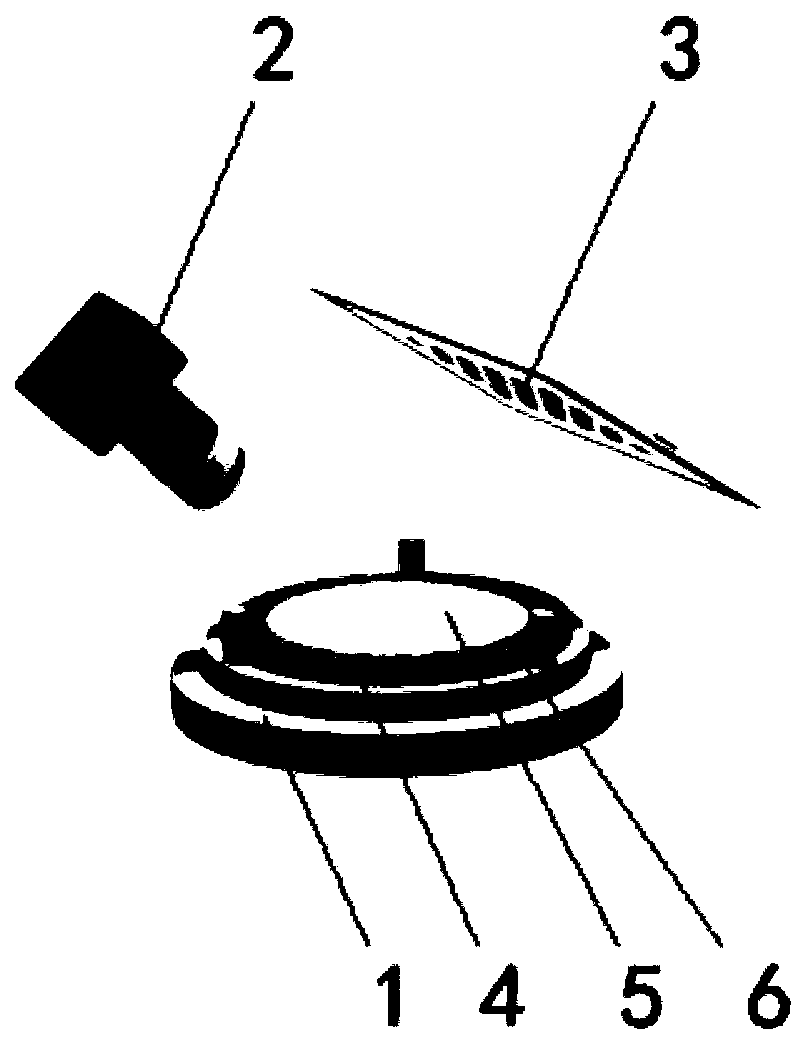
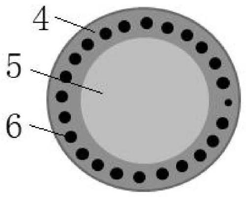
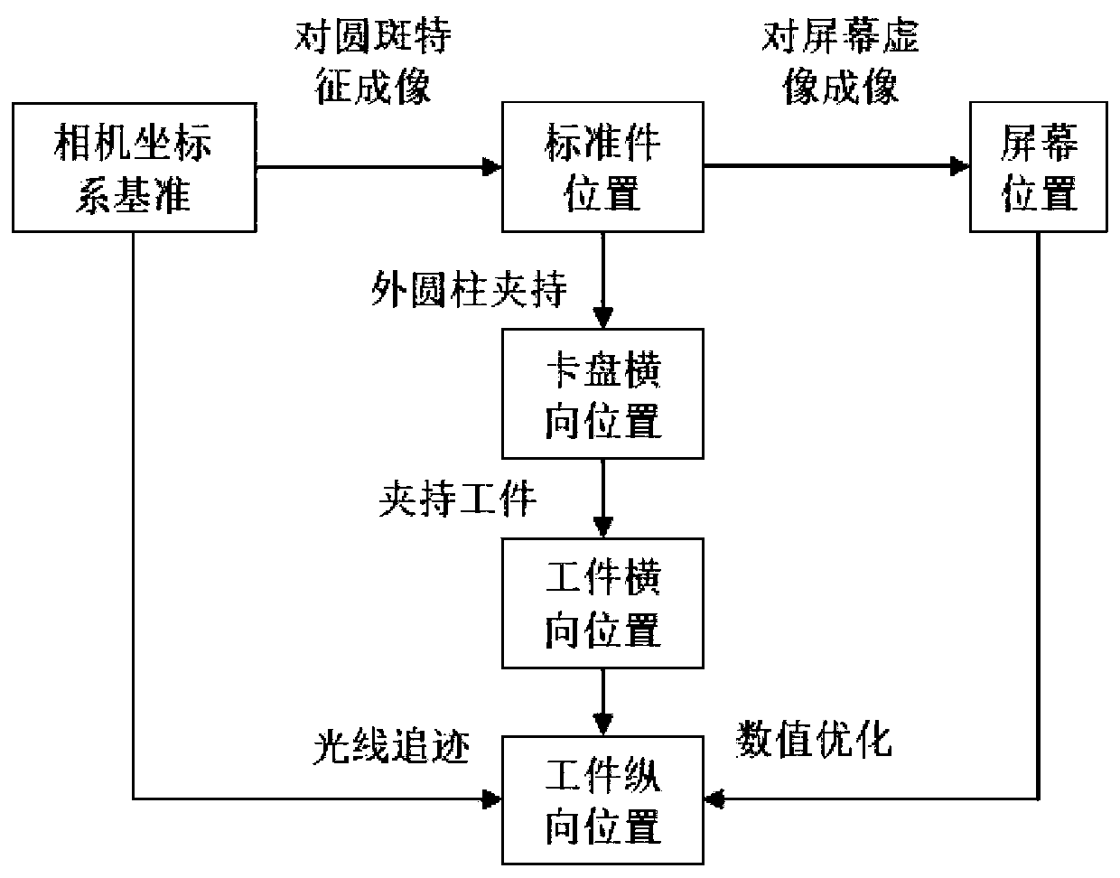
[0039] In order to realize the quick and simple calibration of the deflection measurement system, the ordinary flat mirror is made into a standard part with its own reference for improvement. It is made of aluminum alloy, and the upper part is a cylinder with a diameter of 200mm and a height of 10mm. The upper surface is made of single-point diamond. Turned into a mirror surface, the flatness is better than λ / 5PV. Process 24 circular spots with a diameter of 16mm evenly distributed on the upper surface at φ180mm, one of which is set to a diameter of 10mm, and all the circular spots are blackened, such as figure 1 shown. The pose of the plane mirror is obtained directly through the landmark points on the plane mirror. The screen displays a 20×15 dot array, and the diameter of each dot is set to 15 pixels, according to image 3 Steps to complete the geometric calibration. Measure an aspherical workpiece with a caliber of 130mm, and perform ray tracing from the center of gravi...


PUM


Abstract

The invention relates to the technical field of optical engineering, and further discloses a calibration method for rapidly determining the geometric position of each part in the deflection measurement system. The method comprises: making the upper plane of a standard cylinder into a standard mirror surface, making a circle of evenly-distributed black round spot features on the periphery of the standard mirror surface, the radius of one round spot being small, setting the mirror surface to be a coordinate system xOy plane, and the x axis being arranged on the axis where the round spot is located; firstly, directly determining the position of a standard mirror surface in a camera coordinate system through a PnP method according to imaging of mirror surface circular spots, displaying a small-size dot array pattern on a screen, shooting a screen virtual image reflected by the mirror surface through a camera, recognizing spots displayed on the screen in the image, and the position of the screen can be determined. The method can effectively estimate the pose of each part in the measurement system, including a camera, a screen, a chuck and a workpiece, is simple to operate and high in practicability, and has important significance for realizing high-precision deflection measurement of the optical curved surface.

Description

technical field [0001] The invention relates to the technical field of optical engineering, in particular to a calibration method for rapidly determining the geometric positions of components in a deflection measurement system. Background technique [0002] In modern precision measurement, interferometry is commonly used for mirror-reflective surfaces. However, its measuring range is small and sensitive to environmental interference, so it is not suitable for the measurement of complex curved surfaces. In recent years, phase measurement deflectometry has achieved high-precision measurement of complex curved surfaces. Because of its simple system, large dynamic range and strong anti-interference ability, it has attracted extensive attention in the field of optical engineering. The principle is to generate regular stripes on the display, and the stripes will be deformed after being reflected by the measured surface. The deformation pattern is taken by a CCD camera, and the s...

Claims


Application Information

Patent Timeline
Patent Type & Authority Applications(China)
IPC IPC(8): G01B11/00G01B11/06G01B11/03G06T7/80
CPCG01B11/002G01B11/03G01B11/0608G06T7/80
Inventor 张祥朝牛振岐叶俊强
Owner FUDAN UNIV
Why Eureka
Try Eureka