A high-speed electrical connector

An electrical connector and high-speed technology, which is applied in the direction of connection and connection device components, circuits, etc., can solve problems such as signal crosstalk, system impedance mismatch, and incomplete shielding of differential signal pairs, so as to reduce manufacturing costs and improve signal quality. The effect of transmission capacity

Active Publication Date: 2021-08-24
SHANGHAI AEROSPACE SCI & IND ELECTRIC APPLIANCE RES INST
View PDF0 Cites 0 Cited by
  • Summary
  • Abstract
  • Description
  • Claims
  • Application Information

AI Technical Summary

Problems solved by technology

[0002] High-speed electrical connectors are used to support high-performance applications. Signal shielding and integrity are the key to the entire design; in one-end connectors, the main design is to match the system impedance with the entire connector; impedance matching is the most important part of the transmission signal. Important parameters, such as impedance mismatch, will cause serious signal crosstalk during high-speed signal transmission, unstable signal transmission, and degraded quality;
[0003] High-speed electrical connectors used to support high data rates often use several differential signal pairs. The shielding components in the current connectors do not completely shield the differential signal pairs, and the shielding cost is high; and when connecting, the system impedance will appear differently. The situation of matching will eventually cause the stability and quality of the signal to decline

Method used


Image

  • A high-speed electrical connector
  • A high-speed electrical connector
  • A high-speed electrical connector

Examples


Embodiment Construction

[0029] In order to make the object, technical solution and advantages of the present invention more clear, the present invention will be further described in detail below in conjunction with the examples. It should be understood that the specific embodiments described here are only used to explain the present invention, not to limit the present invention.

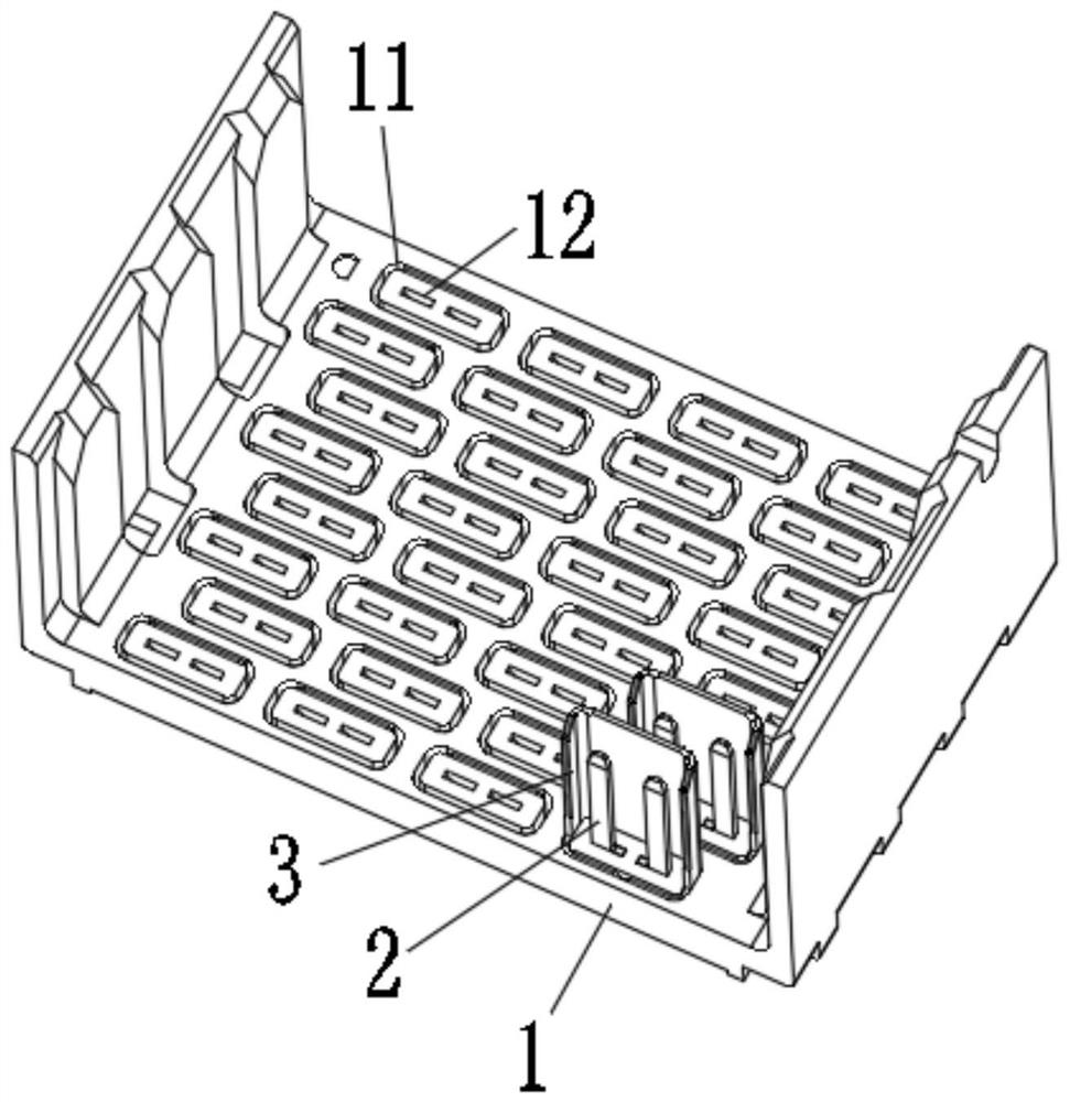
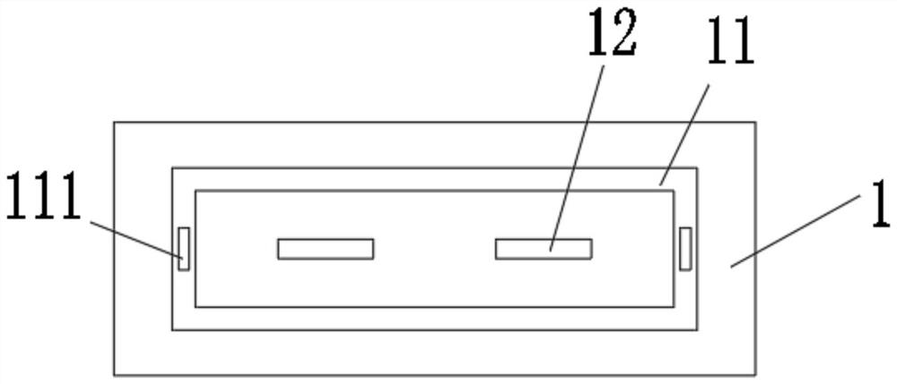
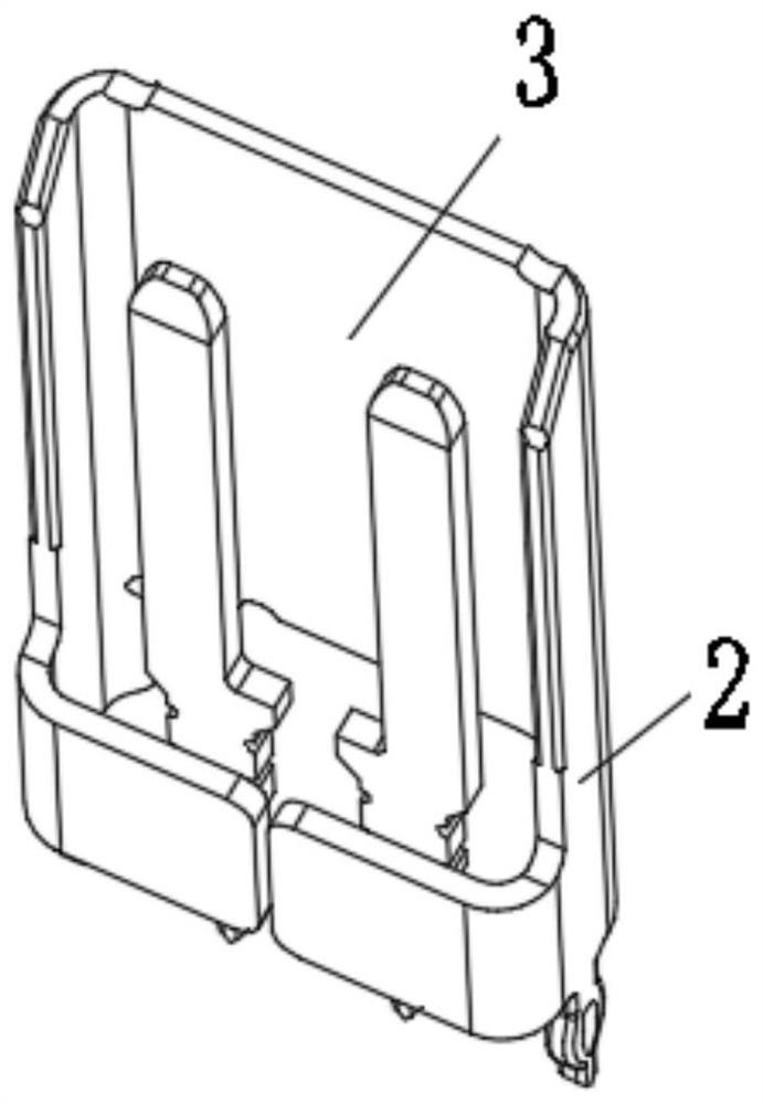
[0030] A high-speed electrical connector, comprising a base 1; a shielding assembly 3 and a differential signal element 2 are plugged into the base 1, the shielding assembly 3 surrounds the outside of the differential signal element 2, and the shielding assembly 3 is used to isolate the external interference of the differential signal part 2;

[0031] The differential signal component 2 includes a first conductor 21 and a second conductor 22 arranged mirror-symmetrically, the first conductor 21 includes a first signal plane 211 and a second signal plane 212, the first signal plane 211 and the The second signal board 212 ha...


PUM


Abstract

A high-speed electrical connector, including that the differential signal element includes a first conductor and a second conductor arranged in mirror image symmetry, the first conductor includes a first signal board and a second signal board, and the first signal board and the The second signal board is an integral structure, the first signal board is arranged on the top of the second signal board, the second signal board protrudes from the base, and the second signal board and the The base is plugged in; the central axis of the first signal board is staggered from the central axis of the second signal board, and the staggered setting is used to match the impedance value; the present invention adopts the differential signal element designed with the central axis staggered, which can avoid the Signal loss caused by impedance mismatch, to achieve differential signal components can match the impedance value.

Description

technical field [0001] The invention belongs to the technical field of communication connectors, in particular to a high-speed electrical connector. Background technique [0002] High-speed electrical connectors are used to support high-performance applications. Signal shielding and integrity are the key to the entire design; in one-end connectors, the main design is to match the system impedance with the entire connector; impedance matching is the most important part of the transmission signal. Important parameters, such as impedance mismatch, will cause serious signal crosstalk during high-speed signal transmission, unstable signal transmission, and degraded quality; [0003] High-speed electrical connectors used to support high data rates often use several differential signal pairs. The shielding components in the current connectors do not completely shield the differential signal pairs, and the shielding cost is high; and when connecting, the system impedance will appear...

Claims


Application Information

Patent Timeline
Patent Type & Authority Patents(China)
IPC IPC(8): H01R13/6474H01R13/6585H01R13/6461H01R13/40
CPCH01R13/40H01R13/6461H01R13/6474H01R13/6585
Inventor 芦伟栾壹侠
Owner SHANGHAI AEROSPACE SCI & IND ELECTRIC APPLIANCE RES INST
Why Eureka
Try Eureka