Positioning of a medical device conductor in an MRI environment to reduce RF induced current

a technology of mri environment and conductor, which is applied in the direction of magnetic measurement, therapy, instruments, etc., can solve the problems of loss of therapy, overheating of lead and adjacent body tissue, and damage to both myocardial tissue and neurological tissue, so as to reduce the amount of induced rf current and measure the increase in heat along the lead electrode.

Active Publication Date: 2015-06-23
WILSON GREATBATCH LTD
View PDF15 Cites 9 Cited by
  • Summary
  • Abstract
  • Description
  • Claims
  • Application Information

AI Technical Summary

Benefits of technology

[0020]Experimental data has been generated that indicates that placement of the conductor lead or medical lead directly affects the degree to which the lead electrodes heat when situated within an active MRI environment. Specifically, the experimental data shows that when the medical lead is positioned about the exterior of the medical device, in

Problems solved by technology

It has been documented that when this current becomes excessive, overheating of the lead and the adjacent body tissue can occur.
There have been cases of damage to both myocardial tissue and neurological tissue.
In some cases, damage severe enough to result in loss of therapy, ablation, brain damage, limb amputations, and the like have occurred.
There have been reports of latent problems with cardiac pacemakers or other AMDs after an MRI procedure, sometimes occurring many days later.
Moreover, there are a number of papers that indicate that the SAR level is not entirely predictive of the heating that would be found in implanted leads or devices.
It is speculated that SAR level alone is not a good predictor of whether or not an implanted device or its associated lead system will overheat.
Variations in the device lead length and implant trajectory can significantly affect how much heat is generated.
Excessive current at the distal electrode to the tissue interface can cause excessive heating to the point where tissue ablation o

Method used


Image

  • Positioning of a medical device conductor in an MRI environment to reduce RF induced current
  • Positioning of a medical device conductor in an MRI environment to reduce RF induced current
  • Positioning of a medical device conductor in an MRI environment to reduce RF induced current

Examples


Embodiment Construction

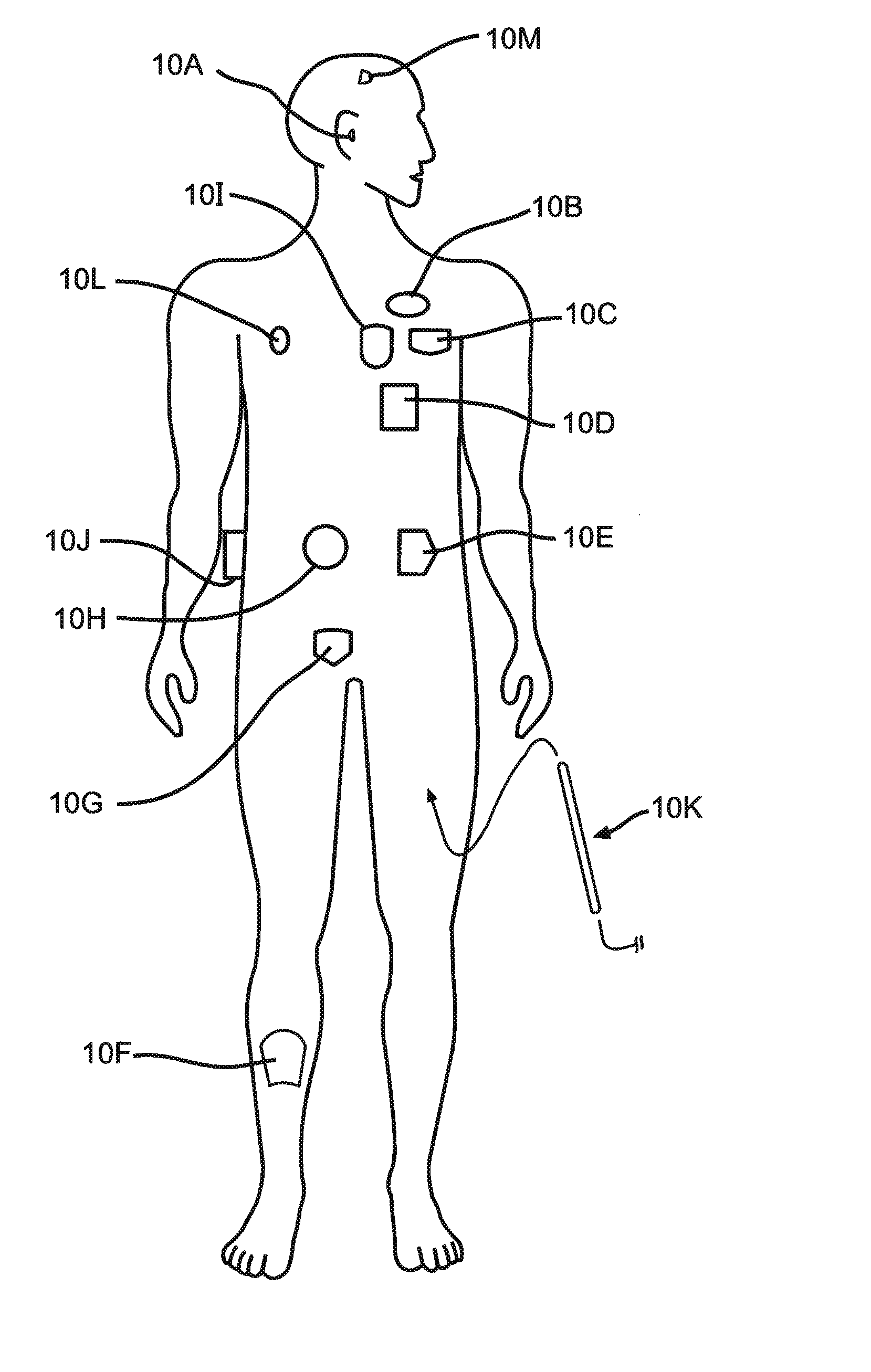
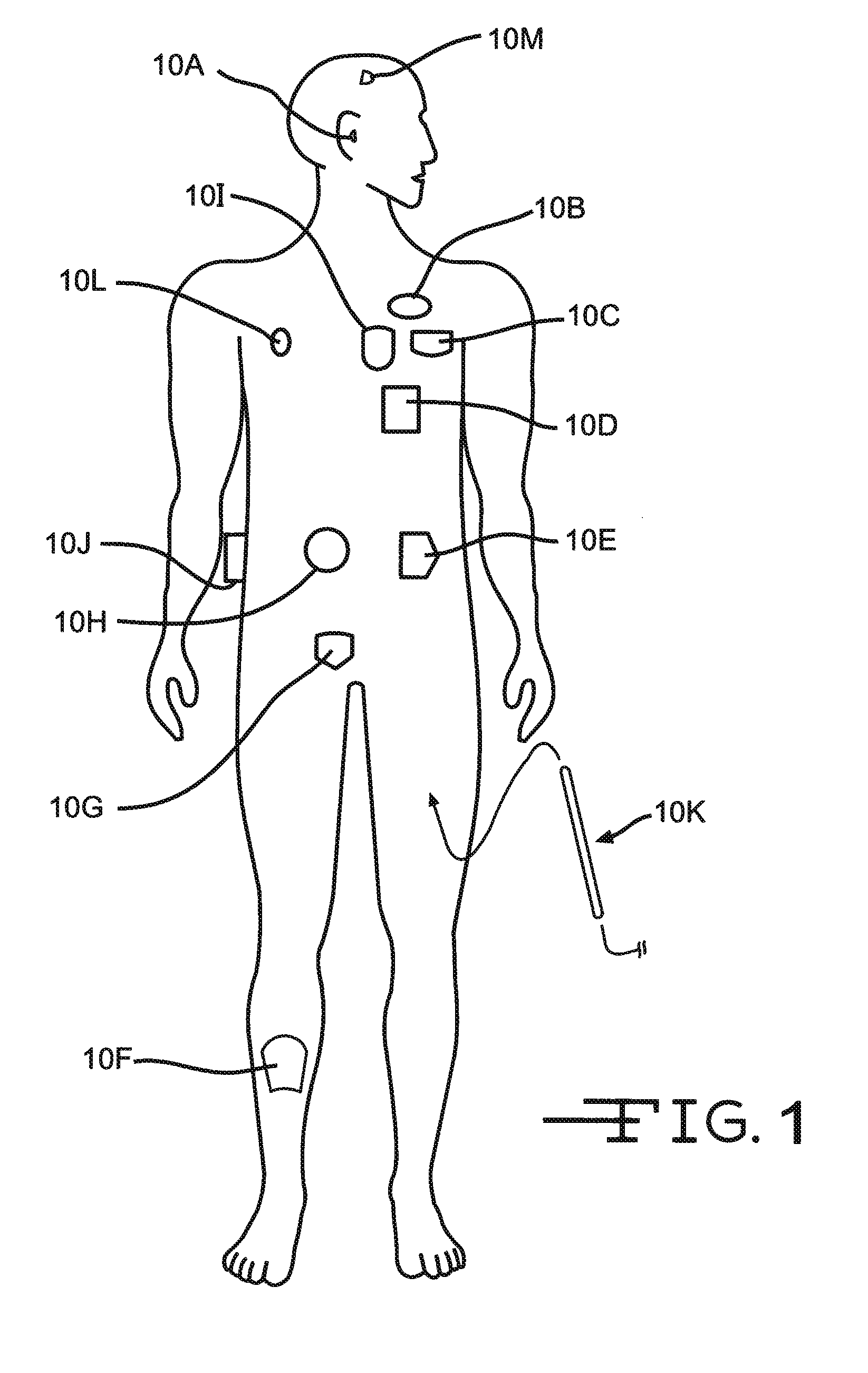
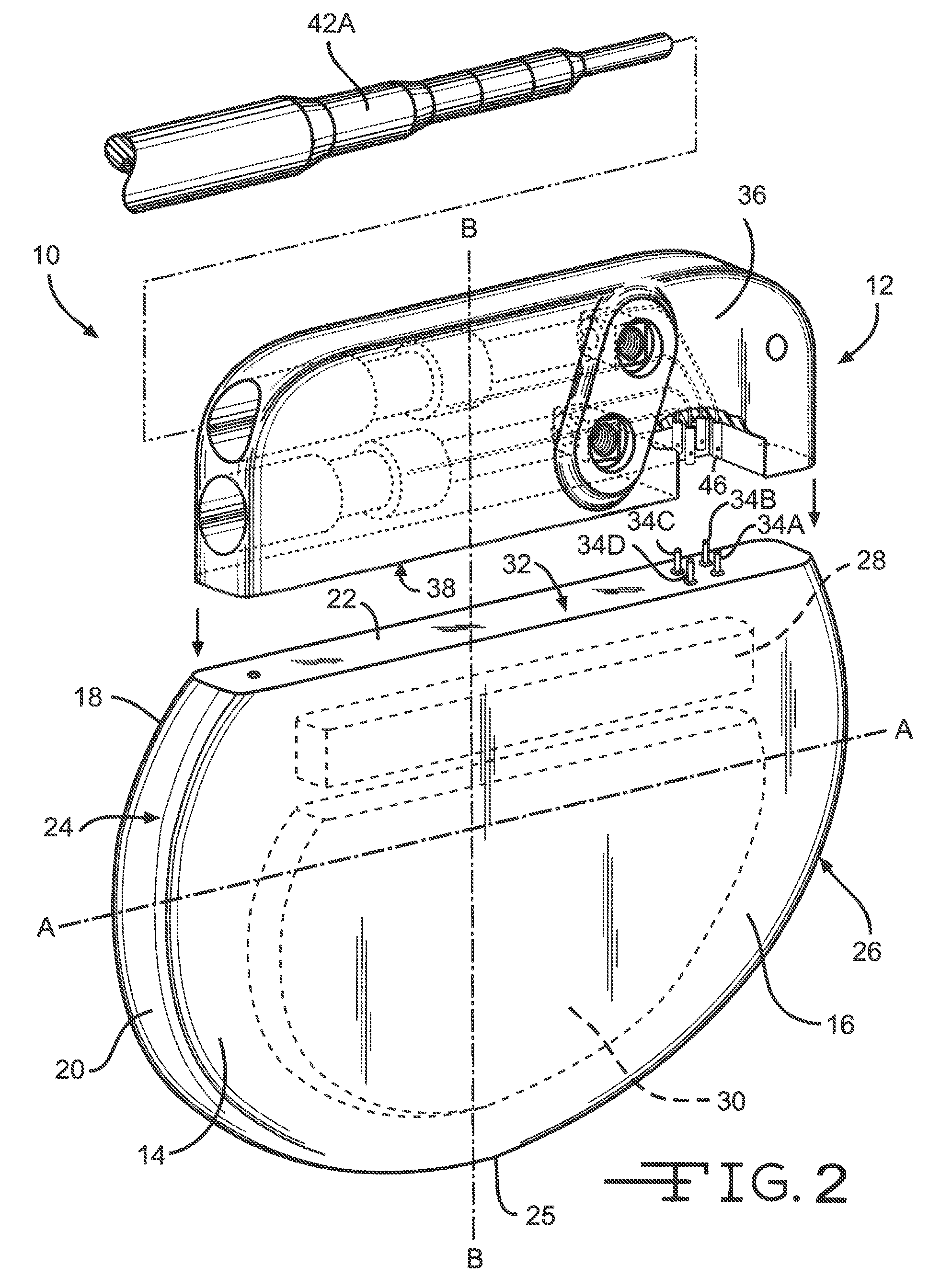
[0038]As shown in the drawings for purposes of illustration, the present invention pertains to the placement of a conductor about an active implantable medical device (AIMD) such that induced RF current heating within the medical lead, particularly of the electrodes of the medical lead, of the connected medical device is reduced. More specifically, the present invention concerns the controlled placement of the conductor about the exterior of an implantable medical device, for example as a cardiac pacemaker, a cardioverter defibrillator, or a neurostimulator, such that when the device is placed within an MRI environment, RF current induced heating within its connected lead is reduced.

[0039]The term “conductor” is herein defined as an electrically conductive pathway. The conductor may comprise a single electrically conductive wire, filar, filled via, conductive trace, such as a conductive line deposited on a surface, or may comprise a plurality of electrically conductive wires, filars...


PUM


Abstract

The present invention provides embodiments in which induced RF current heating along the length of a medical lead is reduced. Reduction of induced RF current heating in the medical lead is achieved by positioning a conductor about the exterior of an implantable medical device when the device is placed within an MRI environment. In one embodiment, an RF conductor is incorporated within a header assembly for connecting an implantable medical device to at least one conductor lead. The body of the RF conductor is positioned circumferentially around the implantable medical device. In another embodiment, the medical lead is positioned circumferentially around the exterior of the housing of the medical device. A series of clips or a sleeve holds the medical lead or RF conductor in place around the device.

Description

CROSS-REFERENCE TO RELATED APPLICATIONS[0001]This application claims priority from U.S. Provisional Patent Application Ser. No. 61 / 444,182, filed Feb. 18, 2011.FIELD OF THE INVENTION[0002]This invention relates generally to a means of positioning a conductor about an implantable medical device such that RF lead tip heating is reduced when the medical device is placed within an MRI environment.BACKGROUND OF THE INVENTION[0003]The radio frequency (RF) pulsed field of MRI can couple to an implanted lead in such a way that electromagnetic forces (EMFs) are induced in the lead. The amount of energy that is induced is related to a number of complex factors, but in general, is dependent upon the local electric field that is tangent to the lead and the integral of the subsequent electric field strength along the lead. In certain situations, these EMFs can cause currents to flow into distal electrodes and through the electrode interface to body tissue. It has been documented that when this c...

Claims


Application Information

Patent Timeline
IPC IPC(8): A61N1/00
CPCA61N1/00A61N1/3718A61N1/375A61N1/086A61N1/37512A61N1/37514G01R33/288
Inventor ZWEBER, JEFFREYJOHNSON, ROBERT SHAWN
Owner WILSON GREATBATCH LTD
Why Eureka
Try Eureka