ESD clamp circuit applied to power amplifier

a technology power amplifier, which is applied in the direction of amplifier, transistor, amplifier, etc., can solve the problems of inadvisable integration of this large inductor into the same ic, signal loss generation, etc., and achieve the effect of avoiding the loss of signal caused by the leakage current of esd clamp circui

Active Publication Date: 2012-05-01
IND TECH RES INST
View PDF5 Cites 9 Cited by
  • Summary
  • Abstract
  • Description
  • Claims
  • Application Information

AI Technical Summary

Benefits of technology

[0014]In the present invention, a first circuit is added between a first line and an ESD detecting unit, and / or a second circuit is added between the first circuit and a buffer unit. Therefore, an ESD clamp unit is turned off effectively, so signal loss caused by the leakage current of ESD clamp circuit can be avoided in a power amplifier.

Problems solved by technology

Therefore, to integrate this large inductor into the same IC is inadvisable.
In addition, if design of conventional power-rail ESD protection is used at normal operation, a problem of signal loss is generated by the power amplifier 100 caused by the leakage current of power-rail ESD clamp circuit 110.

Method used


Image

  • ESD clamp circuit applied to power amplifier
  • ESD clamp circuit applied to power amplifier
  • ESD clamp circuit applied to power amplifier

Examples


Embodiment Construction

[0046]Reference will now be made in detail to the present embodiments of the invention, examples of which are illustrated in the accompanying drawings. Wherever possible, the same reference numbers are used in the drawings and the description to refer to the same or like parts.

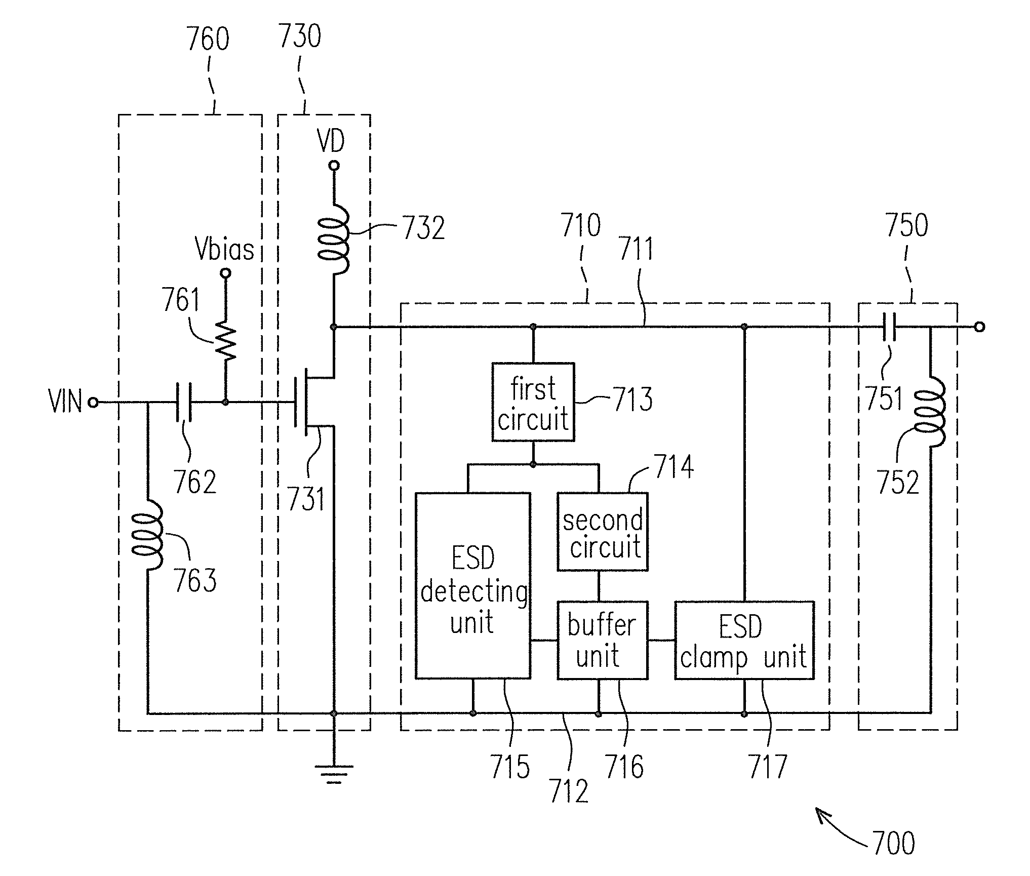
[0047]FIG. 7 is a schematic diagram of a power amplifier device according to an embodiment of the present invention. Referring to FIG. 7, the power amplifier device 700 includes an ESD clamp circuit 710, a power amplifier 730, a matching network 750 and 760. the ESD clamp circuit 710 includes a first line 711, a second line 712, a first circuit 713, a second circuit 714, an ESD detecting unit 715, a buffer unit 716, and an ESD clamp unit 717.

[0048]The first circuit 713 has a first terminal and a second terminal. The first terminal of the first circuit 713 is coupled to the first line 711. The second circuit 714 has a first terminal and a second terminal. The first terminal of the second circuit 714 is coupled ...


PUM


Abstract

An ESD clamp circuit applied to a power amplifier is provided. The ESD clamp circuit includes a first line, a second line, a first circuit, a second circuit, an ESD detecting unit, a buffer unit, and an ESD clamp unit. The first line is coupled to the output terminal of the power amplifier. The first circuit is coupled to the first line. The second circuit is coupled to the first circuit. The ESD detecting unit is coupled to the first circuit and the second line. The buffer unit is coupled to the second circuit, the second line and the ESD detecting unit. The ESD clamp unit is coupled to the buffer unit, the first line and the second line. Therefore, at normal operation mode, the problem of signal loss caused by the leakage current of ESD clamp circuit can be avoided.

Description

CROSS-REFERENCE TO RELATED APPLICATION[0001]This application claims the priority benefit of Taiwan application serial no. 97148269, filed on Dec. 11, 2008. The entirety of the above-mentioned patent application is hereby incorporated by reference herein and made a part of this specification.BACKGROUND OF THE INVENTION[0002]1. Field of the Invention[0003]The present invention generally relates to an ESD clamp circuit, and more particularly, to an ESD clamp circuit that can avoid the problem of signal loss caused by the leakage current.[0004]2. Description of Related Art[0005]Nowadays, the manufacture process technology of complementary metal-oxide semiconductor (CMOS) device is developed to nano-meter scale. In order to combine with other CMOS circuit to achieve a design of system-on-a-chip (SOC), a radio frequency (RF) circuit designed by the manufacture process of SiGe would be substituted by the manufacture process of CMOS. In order to discharge ESD current effectively, ESD protec...

Claims


Application Information

Patent Timeline
Patent Type & Authority Patents(United States)
IPC IPC(8): H02H9/00
CPCH01L27/0266H03F1/523H03F2200/441
Inventor YEH, CHIH-TINGLIANG, YUNG-CHIHCHEN, SHIH-HUNG
Owner IND TECH RES INST
Why Eureka
Try Eureka