
A hammering type bearing cage pressing device
A technology of a bearing cage and a press-fitting device, applied in the field of bearing manufacturing, can solve the problem of taking a long time and the like
- Summary
- Abstract
- Description
- Claims
- Application Information
AI Technical Summary
Problems solved by technology
Method used
Image

Examples
Embodiment 1
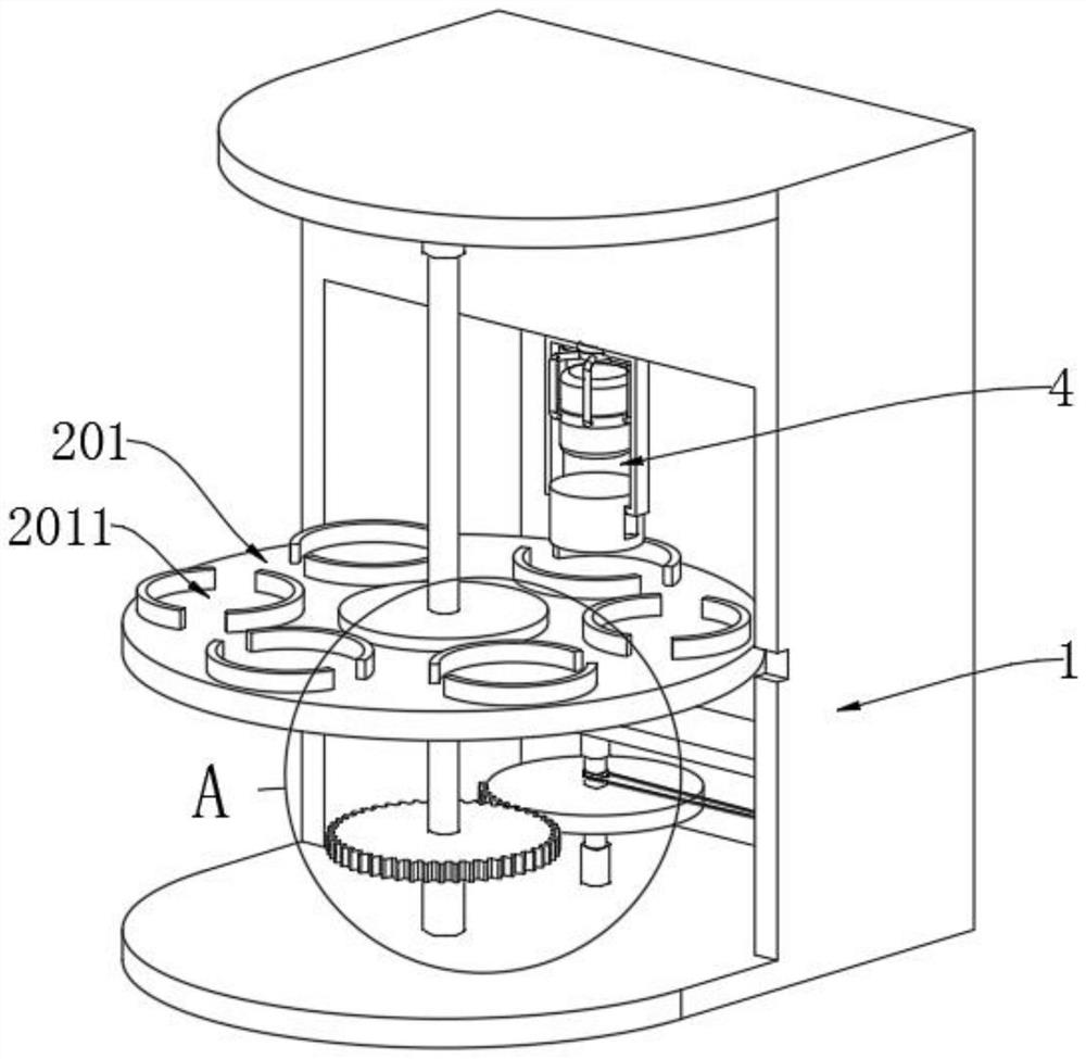
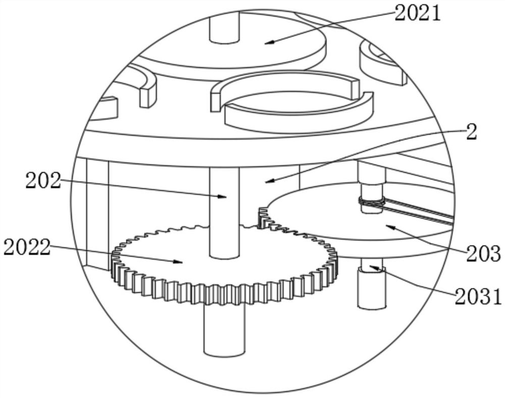
[0032] as attached figure 1 to attach image 3 , Figure 5 with Figure 7 with Figure 8 Shown:
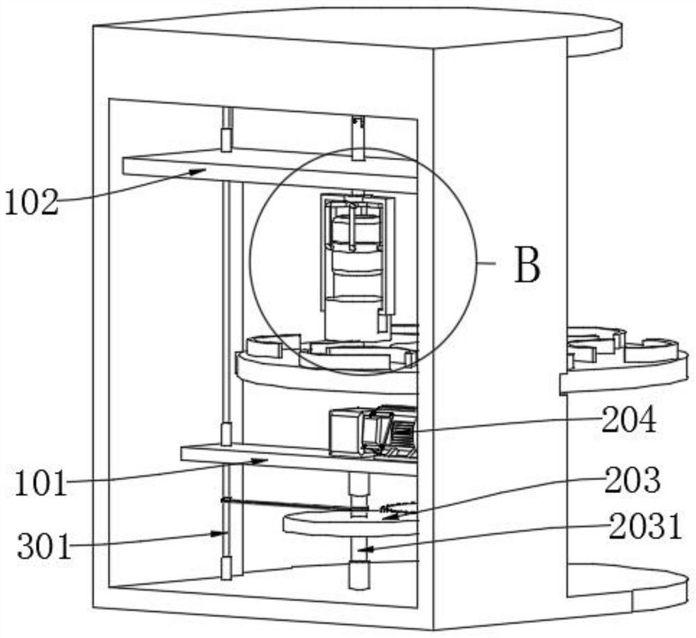
[0033] The invention provides a hammering type bearing cage press-fitting device, which includes a bearing clamping intermittent rotation mechanism 2, the bearing clamping intermittent rotation mechanism 2 is installed in the middle of the front side of the work frame 1, and the bearing clamping intermittent rotation mechanism 2 passes through The linkage mechanism 3 is in transmission connection with the hammer pressing mechanism 4 , and the rear side end of the working frame 1 is connected with a lower partition 101 and an upper partition 102 respectively.
[0034] Among them, the bearing clamping intermittent rotation mechanism 2 includes a turntable 201, a bearing slot 2011, an intermittent rotating shaft 202, a locking plate 2021, and a linkage gear 2022. Also be provided with clamping plate 2021, also be provided with six sets of bearing slots 2011 on the top side of tu...
Embodiment 2
[0037] On the basis of embodiment 1, as attached Figure 6 Shown:
[0038]The present invention provides a hammer type bearing cage pressing device. The linkage mechanism 3 includes a vertical transmission shaft 301, a vertical bevel gear 3011, a horizontal transmission shaft 302, a horizontal bevel gear 3021, a crank 303 and a crank connecting rod 3031. A vertical bevel gear 3011 is clamped to the upper end of the transmission shaft 301, and the lower end of the vertical transmission shaft 301 passes through the upper partition 102 and the lower partition 101 downwards and is rotated and embedded in the rotating cylinder of the work frame 1, and the horizontal The transmission shaft 302 is rotatably installed on the upper end side of the work frame 1 and is clamped with a transverse bevel gear 3021, and the transverse bevel gear 3021 is meshed with the vertical bevel gear 3011, and the crank 303 is also rotatably installed on the upper end side of the work frame 1 and connect...
Embodiment 3
[0041] On the basis of embodiment 1 and embodiment 2, as attached Figure 4 And attached Figure 9 Shown:
[0042] The present invention provides a hammering type bearing cage pressing device. The hammering pressing mechanism 4 includes a rubber hammer 401, an annular ferrule 4011, an L-shaped connecting rod 4012, and an adjusting rod 402. The middle of the rubber hammer 401 is clamped with a The annular ferrule 4011, and the outer circumference of the annular ferrule 4011 is connected with six sets of L-shaped connecting rods 4012, the lower end of the adjusting rod 402 is connected to the middle of the top of the L-shaped connecting rod 4012, and the upper end of the adjusting rod 402 passes through the upper partition 102 Hinged on the crank connecting rod 3031, when the crank 303 rotates, the rubber hammer 401 can be moved downwards driven by the crank connecting rod 3031, wherein the hammer pressing mechanism 4 also includes a U-shaped sliding frame 403 and a rubber pad ...
PUM
 Abstract
Description
Claims
Application Information