Three-phase asynchronous motor rotor mandrel press fitting device

A three-phase asynchronous, motor technology, applied in workpiece clamping devices, metal processing equipment, metal processing and other directions, can solve the problems of easy deviation of the iron core, low positioning accuracy, fixed effect, etc., to improve the movement stability, The effect of improving press-fitting accuracy and improving positioning accuracy

Active Publication Date: 2022-03-11
山东瑞博电机有限公司
View PDF12 Cites 6 Cited by
  • Summary
  • Abstract
  • Description
  • Claims
  • Application Information

AI Technical Summary

Problems solved by technology

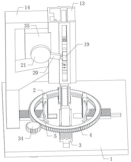
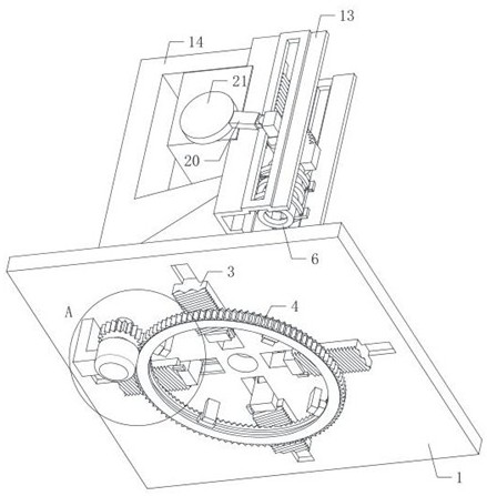
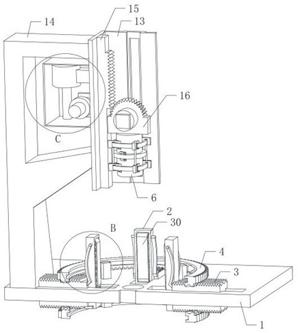
[0002] As we all know, when the rotor in the three-phase asynchronous motor is processed, the motor shaft needs to be pressed into the iron core to form a complete rotor. When the existing press-fitting equipment is used, the iron core is first placed in the mold on the workbench. , and then push the motor shaft through the hydraulic press to insert into the iron core. Since the motor shaft and the tight fit are usually in an interference fit state, the motor shaft and the tight fit are connected to complete the pressing work of the rotor. However, for the convenience of the iron core in the mold Normal movement, the positioning accuracy of the mold to the iron core is low. When the motor shaft is press-fitted with the iron core, the deviation distance between the axis of the motor shaft and the axis of the iron core is relatively large, which may easily cause the motor shaft to be out of alignment with the iron core during press-fitting. The iron core collides, resulting in damage to the parts, and at the same time, the mold cannot fix the iron core, which causes the iron core to easily shift during press-fitting, affecting the normal press-fitting work of the iron core and the motor shaft

Method used


Image

  • Three-phase asynchronous motor rotor mandrel press fitting device
  • Three-phase asynchronous motor rotor mandrel press fitting device
  • Three-phase asynchronous motor rotor mandrel press fitting device

Examples


Embodiment Construction

[0040] The following will clearly and completely describe the technical solutions in the embodiments of the present invention with reference to the accompanying drawings in the embodiments of the present invention. Obviously, the described embodiments are only some, not all, embodiments of the present invention.

[0041]In the description of the present invention, it should be noted that the terms belonging to "center", "upper", "lower", "left", "right", "vertical", "horizontal", "inner", "outer" etc. The indicated orientation or positional relationship is based on the orientation or positional relationship shown in the drawings, and is only for the convenience of describing the present invention and simplifying the description, rather than indicating or implying that the referred device or element must have a specific orientation, or in a specific orientation. construction and operation, therefore, should not be construed as limiting the invention.

[0042] In the description...


PUM


Abstract

The invention relates to the technical field of motor press-fitting equipment, in particular to a three-phase asynchronous motor rotor mandrel press-fitting device which comprises a bottom plate, an auxiliary hole is formed in the middle of the bottom plate, and a plurality of through grooves are evenly formed in the bottom plate and distributed in an annular mode. The length direction of the through groove is along the radial direction of the process hole in the bottom plate; the multiple sets of clamping plates are kept in the vertical direction; the equipment can effectively improve the positioning precision of the iron core, the motor shaft and the iron core can be conveniently kept opposite in position, the situation that the motor shaft collides and damages the iron core when the distance deviation between the axis of the motor shaft and the axis of the iron core is large is avoided, parts are conveniently protected, the press-fitting precision of the equipment is improved, and the production efficiency is improved. And meanwhile, the iron core can be conveniently and synchronously fixed, the situation that the motor shaft cannot be normally pressed into the iron core due to sliding deviation of the iron core caused by stress during press fitting is avoided, the running stability of equipment is improved, and the practicability is improved.

Description

technical field [0001] The invention relates to the technical field of motor press-fitting equipment, in particular to a three-phase asynchronous motor rotor core shaft press-fitting device. Background technique [0002] As we all know, when the rotor in the three-phase asynchronous motor is processed, the motor shaft needs to be pressed into the iron core to form a complete rotor. When the existing press-fitting equipment is used, the iron core is first placed in the mold on the workbench. , and then push the motor shaft through the hydraulic press to insert into the iron core. Since the motor shaft and the tight fit are usually in an interference fit state, the motor shaft and the tight fit are connected to complete the pressing work of the rotor. However, for the convenience of the iron core in the mold Normal movement, the positioning accuracy of the mold to the iron core is low. When the motor shaft is press-fitted with the iron core, the deviation distance between the ...

Claims


Application Information

Patent Timeline
Patent Type & Authority Applications(China)
IPC IPC(8): B23P19/00B23P19/02B25B11/02
CPCB23P19/02B23P19/001B25B11/02
Inventor 于金亮
Owner 山东瑞博电机有限公司
Why Eureka
Try Eureka