
Operation method of compressed air energy storage power station system

A technology of compressed air energy storage and operation method, which is applied to gas turbine devices, liquid variable capacity machinery, pumps, etc., can solve the problems of inability to adjust phase operation, consume external power, and fail to respond quickly to grid dispatching, and avoid heat exchange. The effect is reduced, the response speed is improved, and the effect of avoiding the side bending of the shaft system

Active Publication Date: 2021-03-16
TSINGHUA UNIV
View PDF6 Cites 0 Cited by
  • Summary
  • Abstract
  • Description
  • Claims
  • Application Information

AI Technical Summary

Problems solved by technology

[0006] The purpose of the present invention is to provide a compressed air energy storage power station system and an operation method to solve the problems in the prior art that the compressed air energy storage power station system requires additional consumption of external power for long-term cranking and standby, and cannot respond quickly to power grid scheduling. Technical issues preventing efficient phasing operation

Method used

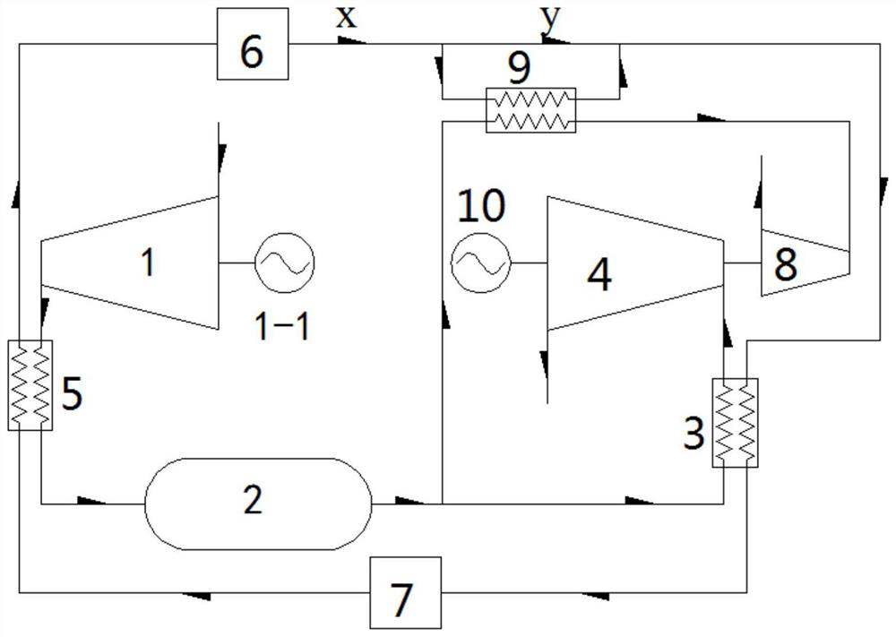

Image

  • Operation method of compressed air energy storage power station system
  • Operation method of compressed air energy storage power station system

Examples


Embodiment Construction

[0024] The specific embodiments of the present invention will be described in further detail below with reference to the accompanying drawings and embodiments. The following examples are intended to illustrate the present invention, but not to limit the scope of the present invention.

[0025] In the description of the present invention, it should be understood that the terms "center", "longitudinal", "lateral", "length", "width", "thickness", "upper", "lower", "front", " Rear, Left, Right, Vertical, Horizontal, Top, Bottom, Inner, Outer, Clockwise, Counterclockwise, Axial, The orientations or positional relationships indicated by "radial direction", "circumferential direction", etc. are based on the orientations or positional relationships shown in the accompanying drawings, which are only for the convenience of describing the present invention and simplifying the description, rather than indicating or implying the indicated devices or elements. It must have a specific orien...


PUM


Abstract

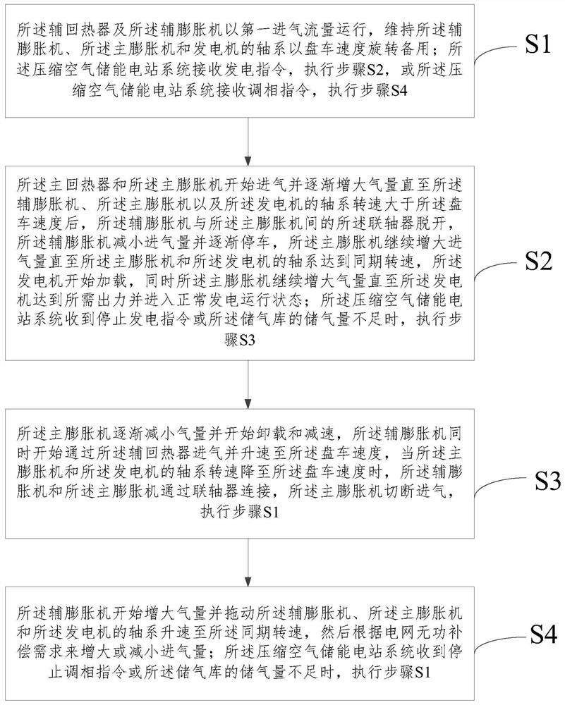
The invention relates to the technical field of energy storage technologies, and discloses a compressed air energy storage power station system and an operation method. The operation method comprisesthe steps that a compressor communicates with a gas storage through the high-temperature side of a cooler, the gas storage communicates with a main expansion machine through the low-temperature side of a main heat regenerator, the cold end and the hot end of the low-temperature side of the cooler correspondingly communicate with a cold accumulator and a heat accumulator, the cold end and the hot end of the high-temperature side of the main heat regenerator correspondingly communicate with the cold accumulator and the heat accumulator, an auxiliary expansion machine is linked or disconnected through a shaft system of a coupling and the main expansion machine, two ends of the low-temperature side of an auxiliary heat regenerator correspondingly communicate with the gas storage and the auxiliary expansion machine, and two ends of the high-temperature side of the auxiliary heat regenerator correspondingly communicate with the heat accumulator and the cold accumulator. According to the compressed air energy storage power station system, the main expansion machine can be in a turning standby state without external energy consumption for a long time, so that a compressed air energy storage power station rapidly responds to the power generation dispatching, and the efficient phasing operation can be carried out.

Description

technical field [0001] The invention relates to the technical field of energy storage, in particular to a method for operating a compressed air energy storage power station system. Background technique [0002] Energy storage, especially the storage of electric energy, is of great significance to the optimization of energy structure and the regulation of power grid operation. Compressed air energy storage system is a new type of energy storage technology. [0003] The working principle of the compressed air energy storage power generation system is similar to that of pumped storage. When the electricity consumption of the power system is at a low point, the system energy storage utilizes the surplus electricity in the system, and the compressor drives the air compressor to compress the air and compress the energy to The form of air is stored in the gas storage device; when the electricity load of the power system reaches a peak and the power generation is insufficient, the ...

Claims


Application Information

Patent Timeline
Patent Type & Authority Patents(China)
IPC IPC(8): F02C1/10F04B41/02
CPCF02C1/10F02C1/105F04B41/02Y02E60/16
Inventor 梅生伟薛小代张学林张通
Owner TSINGHUA UNIV
Learn More