
Building wall structure capable of being cooled for fabricated building

An architectural and prefabricated technology, applied in building components, building structures, buildings, etc., can solve problems such as high power consumption, insufficient energy conservation and environmental protection, and achieve the effects of large heat exchange contact area, increased dependence, and reduced costs.

Active Publication Date: 2020-08-11
安徽研砼建筑科技有限公司
View PDF5 Cites 7 Cited by
  • Summary
  • Abstract
  • Description
  • Claims
  • Application Information

AI Technical Summary

Problems solved by technology

The inner walls of panel buildings are mostly reinforced concrete solid slabs or hollow slabs, and the outer wall panels are mostly reinforced concrete composite panels with insulation layers, which can also be made of lightweight aggregate concrete, foam concrete or macroporous concrete. Facing wall panels. At present, the existing prefabricated building wall structures only have conventional functions such as heat preservation, sound insulation and waterproofing. After the building is used, the indoor temperature is mainly adjusted by heating and cooling appliances (air conditioners, fans, heaters, etc.). High power consumption, not enough energy saving and environmental protection

Method used


Image

  • Building wall structure capable of being cooled for fabricated building
  • Building wall structure capable of being cooled for fabricated building
  • Building wall structure capable of being cooled for fabricated building

Examples


Embodiment Construction

[0023] The following will clearly and completely describe the technical solutions in the embodiments of the present invention with reference to the accompanying drawings in the embodiments of the present invention. Obviously, the described embodiments are only some, not all, embodiments of the present invention.

[0024] In describing the present invention, it should be understood that the terms "upper", "lower", "front", "rear", "left", "right", "top", "bottom", "inner", " The orientation or positional relationship indicated by "outside", etc. is based on the orientation or positional relationship shown in the drawings, and is only for the convenience of describing the present invention and simplifying the description, rather than indicating or implying that the referred device or element must have a specific orientation, so as to Specific orientation configurations and operations, therefore, are not to be construed as limitations on the invention.

[0025] refer to Figure ...


PUM


Abstract

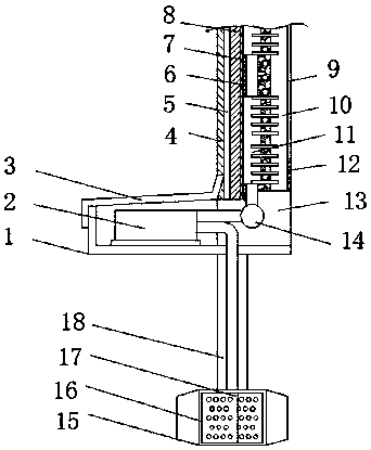
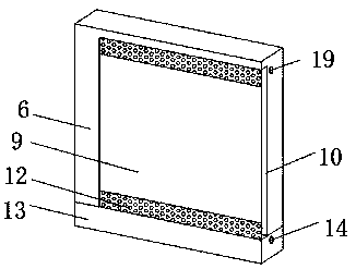
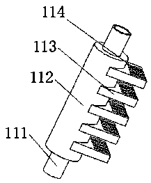
The invention belongs to the technical field of fabricated buildings, particularly relates to a building wall structure capable of being cooled for the fabricated building. In order to solve the problem that an existing fabricated building wall structure only has the conventional functions of heat preservation, sound insulation, water prevention and the like, the following scheme is provided currently. According to the scheme, the building wall structure comprises a seat body, a mounting seat is fixedly mounted at the top of the seat body, a wall body mechanism is arranged at the top end of the mounting seat, and a water return pipe and a water inlet pipe are pre-buried in the top end and the bottom end inside the wall body mechanism correspondingly. According to the building wall structure, through a circulating pump, water can circulate between a water tank and a heat conduction mechanism, the heat conduction mechanism exchanges heat inside a ventilation groove to reduce the internaltemperature, cold air descends inside the ventilation groove, and indoor hot air flow ascends to perform air flow circulation between the indoor space and the ventilation groove, the indoor space iseffectively cooled through circulating water; the circulating water enters the water tank, and due to the fact that the water tank is buried under the ground, the water is cooled through the shady andcool environment under a soil layer.

Description

technical field [0001] The invention relates to the technical field of prefabricated buildings, in particular to a cooling building wall structure for prefabricated buildings. Background technique [0002] Prefabricated building refers to the transfer of a large number of on-site operations in the traditional construction method to the factory, where the building components and accessories (such as floors, wall panels, stairs, balconies, etc.) are processed and manufactured in the factory, and transported to the construction site. Reliable connections are assembled and installed on site. Prefabricated buildings mainly include prefabricated concrete structures, steel structures, modern wooden structures, etc., because of the use of standardized design, factory production, assembly construction, information management, and intelligent applications, they are representatives of modern industrial production methods. [0003] The prefabricated building wall structure is assembled...

Claims


Application Information

Patent Timeline
IPC IPC(8): E04B2/00E04B1/74E04B1/80B01D36/02F24F5/00F24F13/30
CPCB01D36/02E04B1/74E04B1/80E04B2/00F24F5/0046F24F13/30F24F2005/0057Y02B10/40
Inventor 周文
Owner 安徽研砼建筑科技有限公司
Learn More