Eureka AIR delivers breakthrough ideas for toughest innovation challenges, trusted by R&D personnel around the world.

Power grid logic wiring diagram generation method and related device

A wiring diagram and logic technology, applied in the field of grid logic wiring diagram generation, can solve problems such as untimely data refresh and current flow stuck.

Pending Publication Date: 2020-07-07
ELECTRIC POWER RESEARCH INSTITUTE, CHINA SOUTHERN POWER GRID CO LTD
View PDF3 Cites 0 Cited by
  • Summary
  • Abstract
  • Description
  • Claims
  • Application Information

AI Technical Summary

Problems solved by technology

[0003] This application provides a grid logic wiring diagram generation method and related devices, which are used to solve the performance problems that the existing PC-based power grid logic wiring diagram drawing method is applied to the large-screen terminal, and the data refresh is not timely and the current flow is stuck. technical issues

Method used


Image

  • Power grid logic wiring diagram generation method and related device
  • Power grid logic wiring diagram generation method and related device
  • Power grid logic wiring diagram generation method and related device

Examples


Embodiment Construction

[0037] In order to enable those skilled in the art to better understand the solution of the present application, the technical solution in the embodiment of the application will be clearly and completely described below in conjunction with the accompanying drawings in the embodiment of the application. Obviously, the described embodiment is only It is a part of the embodiments of this application, not all of them. Based on the embodiments in this application, all other embodiments obtained by persons of ordinary skill in the art without making creative efforts belong to the scope of protection of this application.

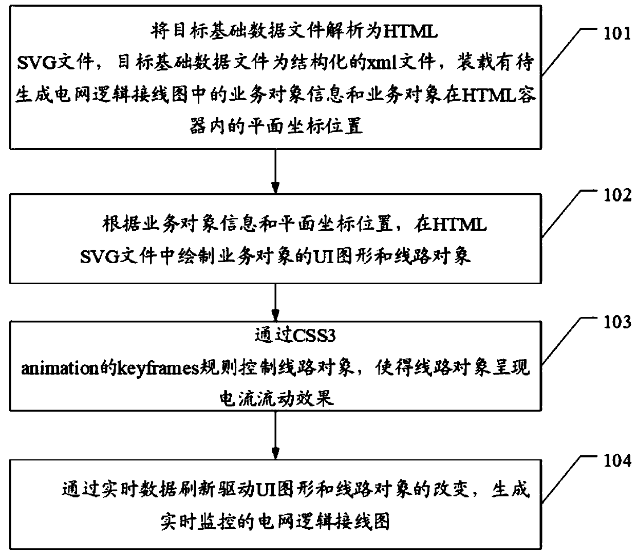
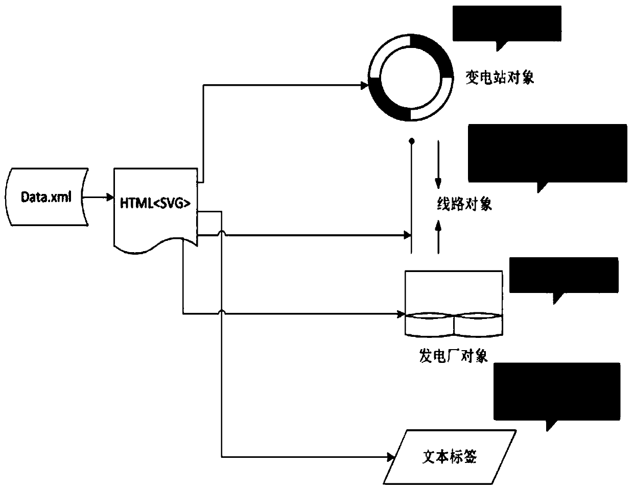
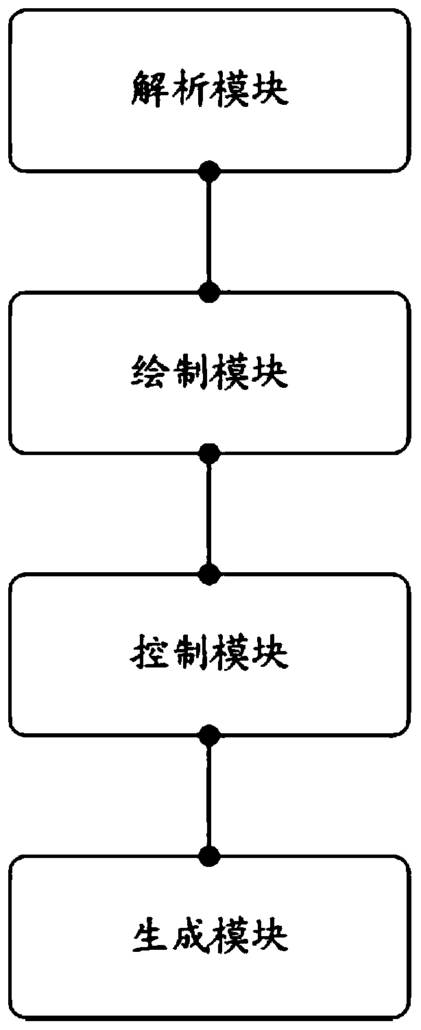
[0038] For ease of understanding, see figure 1 with figure 2 , an embodiment of a method for generating a grid logic wiring diagram provided by the present application, including:

[0039] Step 101. Parse the target basic data file into an HTML SVG file. The target basic data file is a structured xml file, which is loaded with the business object information and...


PUM


Abstract

The invention discloses a power grid logic wiring diagram generation method and a related device. The method comprises the steps of analyzing a target basic data file for obtaining an HTML SVG file, the target basic data file is a structured xml file, and business object information in a power grid logic wiring diagram to be generated and the plane coordinate position of a business object in an HTML container are loaded; drawing a UI graph and a line object of the business object in an HTML SVG file according to the business object information and the plane coordinate position; controlling theline object through a keyframe rule of CSS3 interaction, so that the line object presents a current flowing effect; and refreshing the drive UI graph and the change of the line object through real-time data, and generating a power grid logic wiring diagram monitored in real time. The technical problems that when an existing power grid logic wiring diagram drawing method based on a PC terminal isapplied to a large screen terminal, data refreshing is not timely, and current flowing is not smooth are solved.

Description

technical field [0001] The present application relates to the technical field of electric power scheduling data visualization, and in particular to a method for generating a power grid logical wiring diagram and a related device. Background technique [0002] In the current method of drawing power grid logic wiring diagrams on the computer side, WPF technology, QT technology, HTML5 technology, etc. are used. High, generally above 16K, even as high as 20K, while requiring high graphics card drawing capabilities, there are also high requirements for software implementation methods, and the original PC-based power grid logic wiring diagram drawing method is applied to large-screen terminals There will be performance problems such as untimely data refresh and current flow freeze. Contents of the invention [0003] This application provides a grid logic wiring diagram generation method and related devices, which are used to solve the performance problems that the existing PC-b...

Claims


Application Information

Patent Timeline
Patent Type & Authority Applications(China)
IPC IPC(8): G06F8/38G06F16/957
CPCG06F8/38G06F16/957
Inventor 肖勇郑楷洪赵云钱斌周密
Owner ELECTRIC POWER RESEARCH INSTITUTE, CHINA SOUTHERN POWER GRID CO LTD
Why Eureka
Eureka Blog
Learn More