Redundancy error correction structure of OTP

A technology of redundant error correction and redundant storage, applied in the field of redundant error correction structure, which can solve the problems of reducing the error correction rate, unable to correct at the same time, and wasting the area of ​​storage space.

Active Publication Date: 2020-07-07
58TH RES INST OF CETC
View PDF3 Cites 2 Cited by
  • Summary
  • Abstract
  • Description
  • Claims
  • Application Information

AI Technical Summary

Problems solved by technology

[0003] The purpose of the present invention is to provide a redundant error correction structure of OTP, to solve the problem that the existing storage array structure proposed in the above background technology wastes more than double the area of ​​storage space, and the judgment condition can only correct the storage of "0 " or "1" storage unit, the two kinds of errors cannot be corrected at the same time, which reduces the problem of error correction rate

Method used


Image

  • Redundancy error correction structure of OTP

Examples


Embodiment

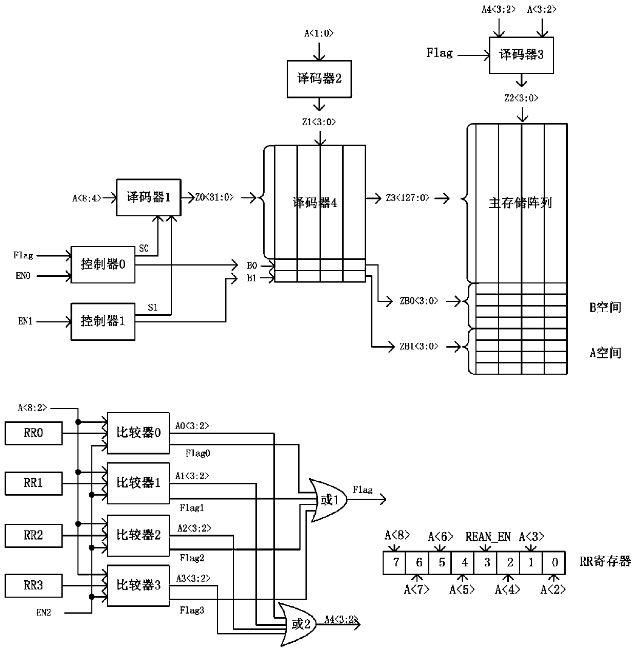
[0013] see figure 1 , this embodiment provides an OTP redundant error correction structure, including a redundant storage array, an address decoding module and a logic control module. The redundant storage array is divided into an A space for storing the address of the damaged storage unit and a B space for replacing the damaged storage unit; the address decoding module is used to decode the input address A, and at the same time Add redundant memory array address during decoding; the logic control module is used to compare the input address with the address of the damaged memory unit stored in the A space, and generate a control signal to control the memory read in the case of damaged memory cells in the main memory array. operate.

[0014] Wherein, the redundant storage array and the main storage array are in the same storage array area. The redundant storage array is divided into 16bytes B space and 16 bytes A space. The address decoding module includes 4 decoders: Decode...


PUM


Abstract

The invention discloses a redundancy error correction structure of an OTP. The redundancy error correction structure comprises a redundancy storage array, an address decoding module and a logic control module. The redundant storage array is divided into a space A for storing addresses of damaged storage units and a space B for replacing the damaged storage units; the address decoding module is used for decoding an input address A (8: 0); and the logic control module is used for comparing the input address with the address of the damaged storage unit stored in the space A, and generating a control signal to control the memory reading operation under the condition that the damaged storage unit occurs in the main storage array. According to the redundancy error correction structure, due to the fact that the error rate of the storage array is low and the redundancy storage space is increased in a targeted mode, waste of the chip area is greatly reduced; damaged storage units are directly replaced, logic judgment is not needed, and errors of all storage data types can be corrected; redundancy error correction is achieved through a register, the error correction speed is high, and efficiency is high.

Description

technical field [0001] The invention relates to the application technical field of memory OTP, in particular to an OTP redundant error correction structure. Background technique [0002] At the heart of memory is the storage array. After the chip is taped out, the storage units in some memories will be physically damaged. Physically damaged storage units cannot store and read normal data. The damage of the memory unit reduces the yield of the memory and increases the production cost. In order to overcome the possible physical damage of the storage array in the memory, structures such as redundant storage and redundant replacement are proposed. Redundant storage uses two or more storage units to store the same data. When reading data, read out the data of these memory cells at the same time, and then make a logical decision on the read out data to obtain the final output data. Such a structure wastes more than double the area of ​​the storage space, and the judgment cond...

Claims


Application Information

Patent Timeline
Patent Type & Authority Applications(China)
IPC IPC(8): G11C29/00
CPCG11C29/78Y02D10/00
Inventor 梁思思任凤霞万书芹叶明远蒋颖丹季惠才薛颜
Owner 58TH RES INST OF CETC
Why Eureka
Try Eureka