Drum angular velocity automatic correction method and automatic correction device

A technology of angular velocity and rotating drum, applied in the direction of television, electrical components, image communication, etc., can solve the problems of low correction accuracy and slow manual correction speed.

Active Publication Date: 2020-07-07
CHANGCHUN INST OF OPTICS FINE MECHANICS & PHYSICS CHINESE ACAD OF SCI
View PDF3 Cites 0 Cited by
  • Summary
  • Abstract
  • Description
  • Claims
  • Application Information

AI Technical Summary

Problems solved by technology

[0006] The purpose of the present invention is to provide an automatic correction method and automatic correction device for the angular velocity of the drum, so a

Method used


Image

  • Drum angular velocity automatic correction method and automatic correction device
  • Drum angular velocity automatic correction method and automatic correction device
  • Drum angular velocity automatic correction method and automatic correction device

Examples


Embodiment Construction

[0049] The technical solutions in the embodiments of the present invention will be clearly and completely described below in conjunction with the drawings in the embodiments of the present invention, and similar component numbers in the drawings represent similar components. Apparently, the embodiments to be described below are only some of the embodiments of the present invention, not all of them. Based on the embodiments of the present invention, all other embodiments obtained by persons of ordinary skill in the art without creative efforts fall within the protection scope of the present invention.

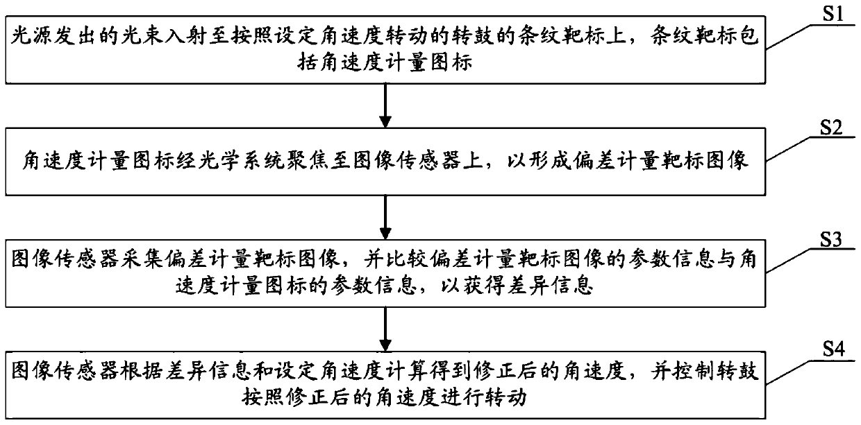
[0050] Figure 1-Figure 5 An embodiment of the method for automatically correcting the drum angular velocity of the present invention is shown. In this example, if figure 1 As shown, the method for automatically correcting the angular velocity of the drum includes the following steps:

[0051] Step S1 , the light beam emitted by the light source is incident on the stripe targ...


PUM


Abstract

The invention discloses a drum angular velocity automatic correction method and an automatic correction device, and the method comprises that: a light beam emitted by a light source enters a stripe target of a drum rotating according to a set angular velocity, and the stripe target comprises an angular velocity metering icon; the angular velocity metering icon if focused to an image sensor throughan optical system to form a deviation metering target image; the image sensor collects a deviation metering target image and compares the parameter information of the deviation metering target imagewith the parameter information of the angular velocity metering icon to obtain difference information; and the image sensor calculates the corrected angular velocity according to the difference information and the set angular velocity and controls the drum to rotate according to the corrected angular velocity. The difference information is obtained in real time according to the parameter information of the deviation measurement target image and the parameter information of the angular velocity measurement icon, and the corrected angular velocity is calculated according to the difference information and the set angular velocity, so that the correction speed of the angular velocity is increased, and the correction accuracy is also improved.

Description

technical field [0001] The invention relates to the technical field of testing equipment, in particular to an automatic correction method and an automatic correction device for the angular velocity of a rotating drum. Background technique [0002] At present, TDI (Time Delayed and Integration) image sensors are used to extract target information under low-light conditions and moving states. By exposing the same target multiple times and delaying the integration time, the collection of light energy is increased, which greatly improves the performance of the target. The ability to recognize low-light scenes and dynamic targets. In order to meet the requirements of work and use, there is a high requirement for the test accuracy of the dynamic transfer function of the image sensor. [0003] The test method of the dynamic transfer function of the image sensor in the prior art is the drum method. In this test method, the target is placed on the dynamic drum, and the target rotati...

Claims


Application Information

Patent Timeline
IPC IPC(8): H04N17/00
CPCH04N17/002
Inventor 李俊霖杨永强赵宇金辉
Owner CHANGCHUN INST OF OPTICS FINE MECHANICS & PHYSICS CHINESE ACAD OF SCI
Why Eureka
Try Eureka