Improved hydraulic rivet machine

An improved riveting machine technology, which is applied in the field of hydraulic machinery, can solve problems affecting riveting speed, achieve the effects of improving riveting quality, improving riveting efficiency, and simplifying the riveting process

Pending Publication Date: 2020-07-10
李振宝
View PDF0 Cites 0 Cited by
  • Summary
  • Abstract
  • Description
  • Claims
  • Application Information

AI Technical Summary

Problems solved by technology

The deficiencies in these two aspects ha

Method used


Image

  • Improved hydraulic rivet machine
  • Improved hydraulic rivet machine
  • Improved hydraulic rivet machine

Examples


Embodiment 1

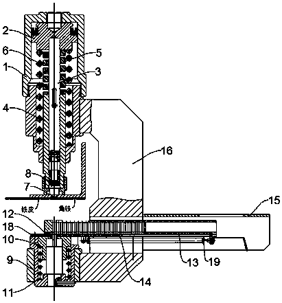
[0022] see Figure 2~3 , in the embodiment of the present invention, an improved hydraulic rivet machine includes a frame 16, and the two ends of the frame 16 are respectively equipped with a cylinder body 1 and a bracket 9, and the bracket 9 is provided with a rivet seat 10; The cylinder 1 is provided with a piston 2 and a composite piston rod matched with it, wherein the piston 2 is connected to the inner wall of the lower end of the cylinder 1 through a return spring 6. During operation, hydraulic oil enters the cylinder 1 and pushes the piston 2 to Moving down, the return spring 6 is compressed to realize the reset of the piston 2 later.

[0023] The composite piston rod includes a piston rod 3 and a piston rod outer casing 4 that is slidingly sleeved on the periphery of the piston rod 3, and the piston rod 3 and the piston rod outer casing 4 are axially limited by a cylindrical pin to prevent the piston rod outer casing 4 from contact with the piston rod outer casing 4. ...

Embodiment 2

[0034] The embodiment of the present invention will carry out the description of the completion workflow of the rivet machine in conjunction with embodiment 1, specifically as follows:

[0035] 1) Install rivets

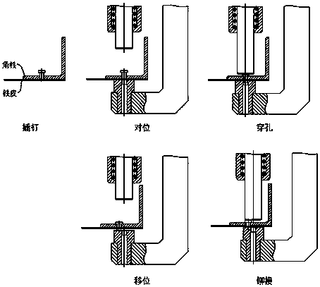
[0036] The rivets are installed in the rivet box 14, and the number of rivets that fill the rivet box 14 is 42. The rivet push plate 13 sends the rivets to the rivet seat 10 through elastic force, and the most front rivet is directly above the push rod 12. This implementation In the example, a rivet with a square end is used, and correspondingly, the upper end surface of the push rod 12 is also square.

[0037] 2) Counterpoint

[0038] Hold the frame 16 in hand, insert the lower part of the piston rod end 7 into the pre-punched hole of the angle iron and make the piston rod 3 substantially perpendicular to the end face of the angle iron hole, so that the rivet can be aligned with the hole on the angle iron, because the piston rod The thrust of the connection spring...


PUM


Abstract

The invention discloses an improved hydraulic rivet machine, which comprises a frame, wherein the two ends of the frame are provided with a cylinder body and a supporting seat respectively; the supporting seat is provided with a rivet seat; the cylinder body is inside provided with a piston and a compound piston rod which cooperate with the cylinder body; the piston is connected to the inner wallof the lower end of the cylinder body by a reset spring; the compound piston rod comprises a piston rod and a piston rod outer sleeve which is arranged on the periphery of the piston rod in a slidingand sleeving manner; the axial limiting is performed between the piston rod and the piston rod outer sleeve by a cylindrical pin; the upper end of the piston rod is fixed to the piston; the lower endof the piston rod is connected to a piston rod end by a connecting spring; and the upper end of the piston rod outer sleeve is connected to the piston by a fast-forward spring. According to the improved hydraulic rivet machine, by arranging the compound piston rod, perforation and riveting can be completed in one-time hydraulic feed; the displacement adjustment does not need to be performed; a riveting procedure is greatly simplified; and the riveting efficiency is increased.

Description

technical field [0001] The invention relates to the field of hydraulic machinery, in particular to an improved hydraulic riveting machine. Background technique [0002] The riveting machine is a device that replaces manual riveting operations. The workflow of the traditional riveting machine is as follows: figure 1 As shown in the figure, it includes five processes of rivet insertion-alignment-perforation-displacement-riveting, in which the riveting of a rivet requires the hydraulic rod to complete two telescopic actions, the first time: Align the center hole of the fixed end of the rivet clamp with the rivet head , and then operate the hydraulic switch to push the hydraulic rod out, so that the rivet head penetrates the iron sheet, and then operate the switch to make the hydraulic rod retract; the second time: avoid the center hole of the rivet clamp fixed end from the rivet head, and repeat the first hydraulic rod action Complete rivet riveting. The deficiencies in these...

Claims


Application Information

Patent Timeline
IPC IPC(8): B21J15/10B21J15/32B21J15/38
CPCB21J15/10B21J15/32B21J15/38
Inventor 李振宝
Owner 李振宝
Why Eureka
Try Eureka