Switch machine indication rod and gap inspection device thereof

An inspection device and a technology of indicating rods are applied in the directions of transportation and packaging, locking mechanisms for turnouts, railway car body parts, etc., which can solve the problem of reducing the tensile strength of the indicating notch position, failure of the notch inspection device, and rust of the notch inspection device. and other problems, to achieve the effect of convenient and quick assembly, reducing external influence and improving anti-loosening performance

Pending Publication Date: 2020-07-10
TAIYUAN JINGFENG RAILWAY EQUIP MANUFCTURING CO LTD
View PDF0 Cites 0 Cited by
  • Summary
  • Abstract
  • Description
  • Claims
  • Application Information

AI Technical Summary

Problems solved by technology

[0002] The gap inspection device for the indicator rod of the existing switch machine is generally arranged on one side of the rod body section of the indicator rod, and the whole gap inspection device is sandwiched between the main and auxiliary indicator rods, and water and Foreign matter can easily lead to rust and jamming of the gap inspection device; the screw on the guide rod is connected to the indicator rod with threads, which has poor anti-loose performance and is easy to fall off, which will lead to the failure of the entire gap inspection device; the shape of the inspection block is a stepped flat plate, and the inspection block A part slides directly under the notch, and a slot needs to be made under the notch, and the weakest part of the mechanical strength of the rod itself is at the notch, and the slot further reduces the tensile strength of the notch.

Method used


Image

  • Switch machine indication rod and gap inspection device thereof
  • Switch machine indication rod and gap inspection device thereof
  • Switch machine indication rod and gap inspection device thereof

Examples


Embodiment Construction

[0023] Hereinafter, exemplary embodiments of the present invention will be described in more detail with reference to the accompanying drawings. Although exemplary embodiments of the present invention are shown in the drawings, it should be understood that the present invention can be implemented in various forms and should not be limited by the embodiments set forth herein. On the contrary, these embodiments are provided for a more thorough understanding of the present invention and to fully convey the scope of the present invention to those skilled in the art.

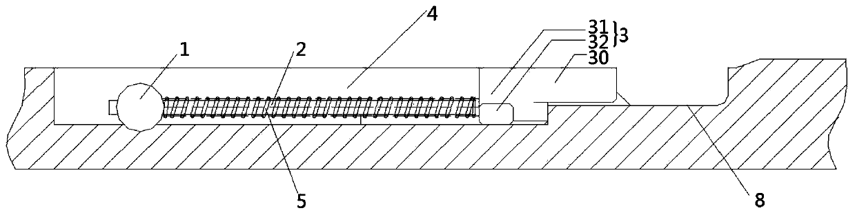
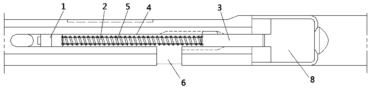
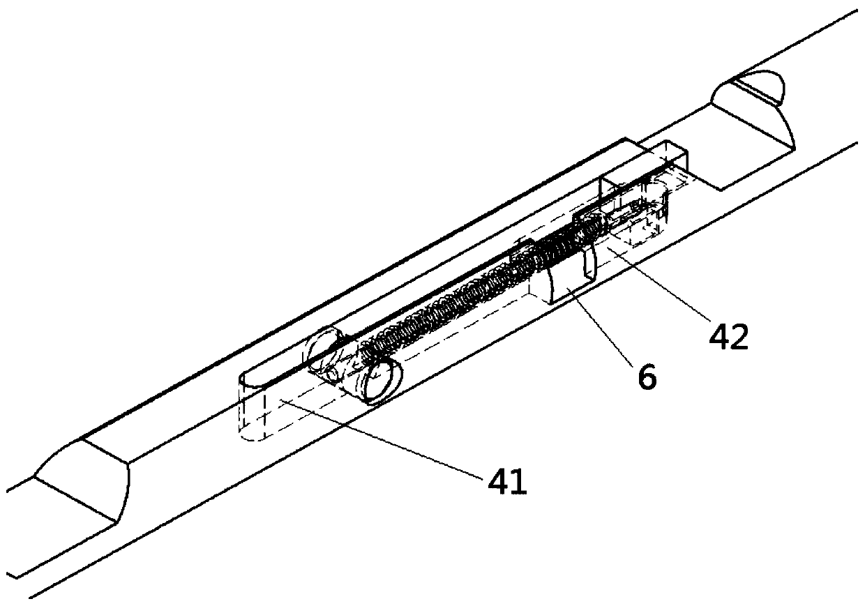
[0024] The present invention provides an embodiment of a switch machine indicating rod, such as Figure 1 to Figure 4 As shown, the indicating rod includes an indicating rod body and an indicating notch 8 provided on the indicating rod body. An axial long slot 4 is opened on the side of the indicating notch 8 of the indicating rod body for installing the notch inspection device, the long slot 4 It includes an axially c...


PUM


Abstract

The invention discloses a switch machine indication rod and a gap inspection device thereof, and belongs to the technical field of switch machines for railway turnouts. The indication rod comprises anindication rod body and an indication gap formed in the indication rod body. An axial long groove is formed in one side of the indication gap of the indication rod body to install a gap inspection device, the long groove comprises a guide groove and an inverted T-shaped groove which are communicated in the axial direction; the inverted T-shaped groove is close to one side of the indication gap; aside gap communicated with the upper part of the inverted T-shaped groove is formed in the inclined plane which is adjacent to the inverted T-shaped groove and represents the gap; the gap inspectiondevice comprises an inspection block capable of sliding in the inverted-T-shaped groove in a reciprocating mode, the upper portion of the side face of the inspection block is integrally connected withan extending end capable of extending out of the side gap, and the extending end is matched with an inspection column of the switch machine to inspect the close attachment state of the turnout. The inverted-T-shaped groove is formed in the center of the indication rod, no groove is formed under the indication gap, and the tensile strength of the indication gap is improved.

Description

Technical field [0001] The invention relates to the technical field of a switch machine for railway turnouts, in particular to a switch machine indicator rod and a gap inspection device thereof. Background technique [0002] The notch inspection device for the indicating rod of the existing switch machine is generally set on one side of the cross section of the indicating rod body. The entire notch inspection device is sandwiched between the main and auxiliary indicating rods. When the main and auxiliary indicating rods move relative to each other, water and Foreign matter can easily cause the notch inspection device to rust and jam; the guide rod nail is connected with the indicator rod by threads, which has poor anti-loose performance and is easy to fall off, which will cause the entire notch inspection device to fail; the shape of the inspection block is a stepped flat plate and the inspection block One part slides directly below the notch, and it needs to be grooved below the...

Claims


Application Information

Patent Timeline
Patent Type & Authority Applications(China)
IPC IPC(8): B61L5/10
CPCB61L5/10
Inventor 边衡施俊明高国栋耿正静赵勇王效毅付雨泽
Owner TAIYUAN JINGFENG RAILWAY EQUIP MANUFCTURING CO LTD
Why Eureka
Try Eureka