Multifunctional emergency respirator for respiratory nursing

A multi-functional, respirator technology, applied in the field of medical care, can solve the problems of not being able to provide water supplement function for patients, reducing the use effect of emergency respirators, and increasing the workload of medical staff, so as to improve the stability of gas supply and reduce the workload , improve the effect of diversity

Inactive Publication Date: 2020-07-14
邱风兰
View PDF13 Cites 2 Cited by
  • Summary
  • Abstract
  • Description
  • Claims
  • Application Information

AI Technical Summary

Problems solved by technology

[0002] At present, severe breathing disorders caused by various reasons often occur among acutely ill patients in the Department of Cardiology. Artificial respiration is a very important and most commonly used rescue method for such patients. However, when artificial respiration is required Among the patients, many patients may have different types of infectious diseases, and medical staff face great risks when doing mouth-to-mouth artificial respiration, especially in the cardiology ward. There are emergency respirators to avoid direct contact with patients, ensure their own safety, avoid psychological conflicts, and effectively prevent cross-infection of oral diseases
[0003] However, the existing emergency respirator has a simple structure and a single function, and can only perform simple air filtration, and the air filtration is not thorough. The existing emergency respirator even still needs artificial exhalation to provide gas supply, which leads to difficult operation and gives The workload of medical staff increases, and the gas provided does not have the function of humidification, so it cannot effectively provide water replenishment function for patients at the same time, which greatly reduces the use effect of emergency respirators

Method used


Image

  • Multifunctional emergency respirator for respiratory nursing
  • Multifunctional emergency respirator for respiratory nursing
  • Multifunctional emergency respirator for respiratory nursing

Examples


Embodiment Construction

[0026] The following will clearly and completely describe the technical solutions in the embodiments of the present invention with reference to the accompanying drawings in the embodiments of the present invention. Obviously, the described embodiments are only some, not all, embodiments of the present invention. Based on the embodiments of the present invention, all other embodiments obtained by persons of ordinary skill in the art without making creative efforts belong to the protection scope of the present invention.

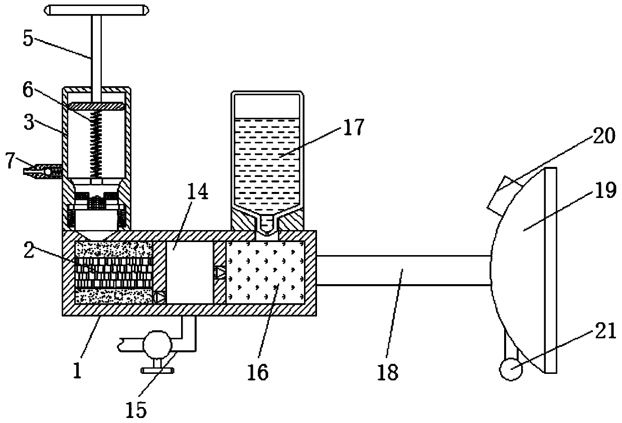
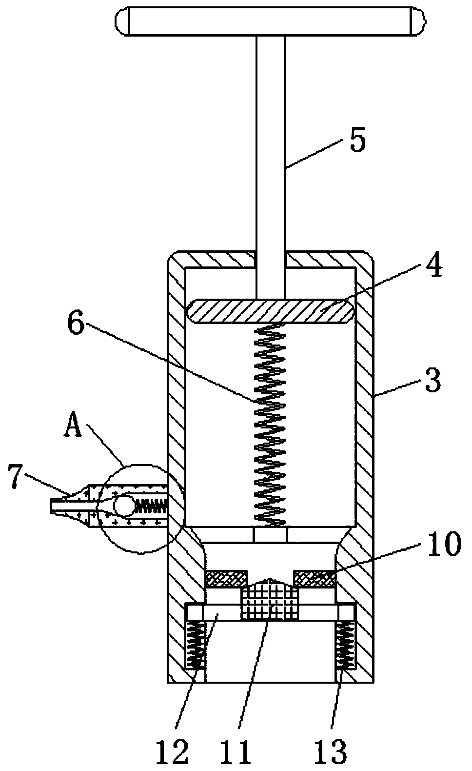
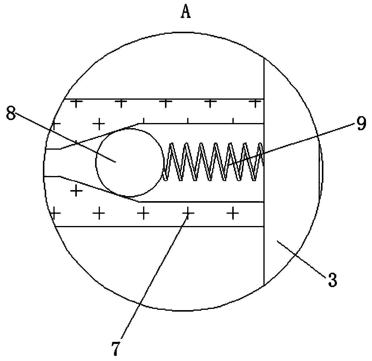
[0027] see Figure 1-4 , a multifunctional emergency respirator for respiratory care, comprising a ventilation box 1, a filter chamber 2, an air injection box 3, a movable piece 4, a push rod 5, a return spring 6, an air inlet nozzle 7, a sphere 8, and a limit spring 9. Sealing ring 10, movable plug 11, fixed frame 12, support spring 13, air intake chamber 14, air intake pipe 15, atomization chamber 16, liquid reservoir 17, connecting pipe 18, breathing mask 1...


PUM


Abstract

The invention relates to the technical field of medical nursing, and discloses a multifunctional emergency respirator for respiratory nursing. The multifunctional emergency respirator comprises a ventilation box; a filter cavity is arranged in the ventilation box; a gas injection box is fixedly connected to the top of the filter cavity; a movable sheet is movably connected to the inside of the gasinjection box; a push rod is fixedly connected to the top of the movable sheet; a reset spring is fixedly connected to the bottom of the movable sheet; a gas inlet nozzle is fixedly connected to theoutside of the gas injection box; a ball body is movably connected to the inside of the gas inlet nozzle; a limiting spring is fixedly connected to the outside of the ball body; and a sealing ring isfixedly connected to the inner bottom of the gas injection box. Through match use of the gas injection box, the movable sheet, the push rod and the reset spring, manual gas supply is achieved, and manual expiratory gas supply of medical personnel is avoided, so that the working burden is reduced, operation difficulty is reduced, stability of gas supply of the emergency respirator is improved, andthe use effect of equipment is ensured.

Description

technical field [0001] The invention relates to the technical field of medical care, in particular to a multifunctional emergency respirator for respiratory care. Background technique [0002] At present, severe breathing disorders caused by various reasons often occur among acutely ill patients in the Department of Cardiology. Artificial respiration is a very important and most commonly used rescue method for such patients. However, when artificial respiration is required Among the patients, many patients may have different types of infectious diseases, and medical staff face great risks when doing mouth-to-mouth artificial respiration, especially in the cardiology ward. There are emergency respirators to avoid direct contact with patients, ensure their own safety, avoid psychological conflicts, and effectively prevent cross-infection of oral diseases. [0003] However, the existing emergency respirator has a simple structure and a single function, and can only perform sim...

Claims


Application Information

Patent Timeline
IPC IPC(8): A61M16/00A61M16/10A61M16/16
CPCA61M16/00A61M16/105A61M16/16A61M2205/75
Inventor 古象芳
Owner 邱风兰
Why Eureka
Try Eureka