
Hydrogen fuel cell device with stable-pressure gas supply

A fuel cell and voltage stabilization technology, used in fuel cells, fuel cell additives, circuits, etc., can solve problems such as voltage instability and pressure instability, improve stability, improve air pressure control accuracy, and improve gas supply stability. sexual effect

Pending Publication Date: 2021-01-08
上海华熵能源科技有限公司
View PDF0 Cites 0 Cited by
  • Summary
  • Abstract
  • Description
  • Claims
  • Application Information

AI Technical Summary

Problems solved by technology

[0004] The technical problem to be solved by the present invention is to provide a hydrogen fuel cell device with a stable pressure gas supply to solve the problem of voltage instability caused by hydrogen fuel cells in the prior art in view of the above defects

Method used


Image

  • Hydrogen fuel cell device with stable-pressure gas supply
  • Hydrogen fuel cell device with stable-pressure gas supply
  • Hydrogen fuel cell device with stable-pressure gas supply

Examples


Embodiment 1

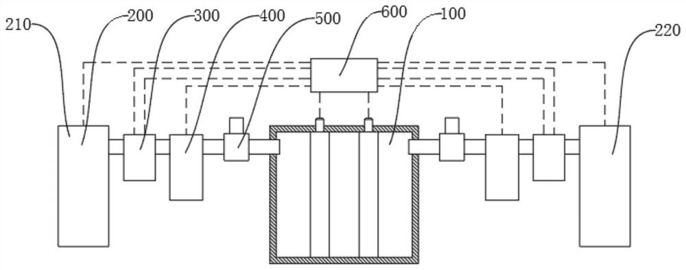
[0024] Depend on figure 1 As shown, a hydrogen fuel cell device with stable pressure gas supply includes a reaction unit 100, and the reaction unit 100 is used for electrochemical reaction of hydrogen and oxygen. The reaction unit 100 is provided with an anode, a cathode and an electrolyte, and the hydrogen Passing in from the anode, oxygen passing in from the cathode, hydrogen and oxygen undergo an electrochemical reaction in the reaction unit 100 to generate electricity;

[0025] A gas storage unit 200, the gas storage unit 200 is used to store reactants, the gas storage unit 200 includes a hydrogen storage module 210, the hydrogen storage module 210 is used to store hydrogen, in some examples, the hydrogen storage module 210 is a hydrogen storage Can;

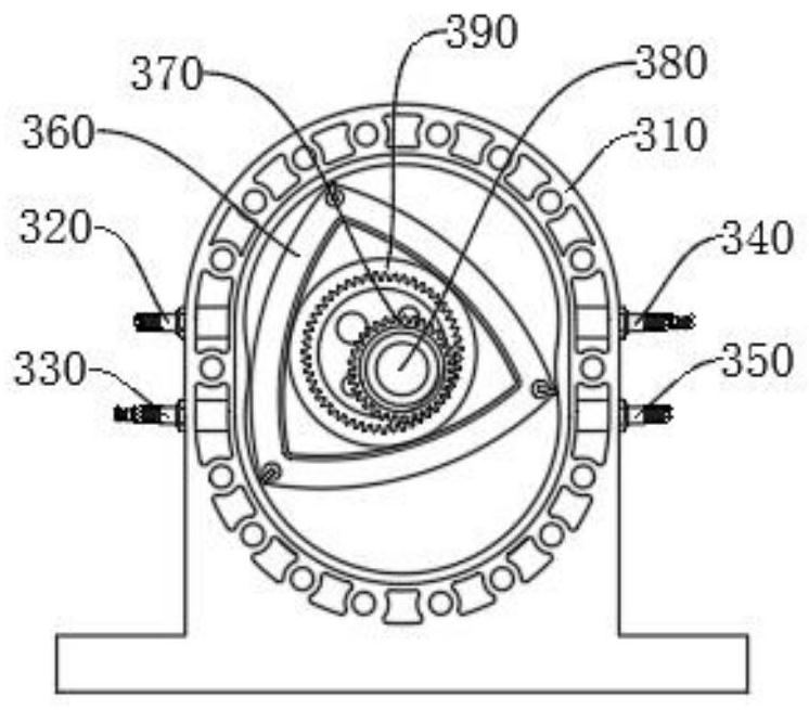
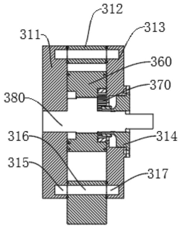
[0026] Gas supply unit 300, the gas supply unit 300 provides stable pressure for the reaction unit 100, so that the voltage generated by the reaction unit 100 is stable, the gas supply unit 300 is provided with two groups, ...

Embodiment 2

[0043] As another embodiment of the present invention, the reaction unit 200 further includes an oxygen storage module 220, and oxygen is stored in the oxygen storage module 220. In some examples, the oxygen storage module 220 is an oxygen tank; the oxygen storage module communicate with the gas supply unit 300 connected to the cathode of the reaction unit 100;

[0044] Other structures in this embodiment are the same as those in Embodiment 1.

[0045] In summary, the working principle of the present invention is:

[0046] The air supply unit 300 can supply air stably, and the air supply volume of the air supply unit 300 is related to the rotation speed of the driving motor on the air supply unit 300. Since the rotation speed of the air supply unit 300 is a linear control amount, the air supply unit 300's air supply The amount can be linearly controlled, so that the control unit 600 can control the air supply volume of the air supply unit 300, and at the same time, the contro...


PUM


Abstract

The invention discloses a hydrogen fuel cell device for stable-pressure gas supply, relates to the field of hydrogen fuel cells, solves the problem of unstable voltage caused by unstable pressure of ahydrogen fuel cell in the prior art, and has the technical points that the hydrogen fuel cell device comprises a reaction unit; a gas storage unit which is used for storing a reactant; two groups ofgas supply units which are respectively communicated with the anode and the cathode of the reaction unit; a pressure tank which is communicated with the gas supply unit, wherein the gas supply unit isused for filling hydrogen or oxygen into the pressure tank, the pressure tank is communicated with the reaction unit, and the hydrogen or oxygen in the pressure tank is filled into the reaction unit;a pressure stabilizing valve which is arranged on a gas path of the pressure tank and the reaction unit; and a control unit which is provided with a first pressure sensor in the pressure tank, wherein the control unit is electrically connected with the gas supply unit and the reaction unit. According to the invention, the device has the characteristics of stable gas supply and simple control.

Description

technical field [0001] The invention relates to the field of hydrogen fuel cells, in particular to a hydrogen fuel cell device with stable pressure gas supply. Background technique [0002] Fuel cell is a chemical device that directly converts the chemical energy of fuel into electrical energy. It is the fourth power generation technology after hydropower, thermal power and atomic power. Because fuel cells use fuel and oxygen as raw materials; at the same time There are no mechanical transmission parts, so there is no noise pollution, and the emission of harmful gases is very small. It can be seen that from the point of view of saving energy and protecting the ecological environment, fuel cells are the most promising power generation technology. [0003] The hydrogen-oxygen fuel cell uses a gas pump to supply reactants. Since the voltage of the fuel cell is related to the gas supply pressure, when the gas supply pressure is unstable, it is easy to cause the pressure of the ...

Claims


Application Information

Patent Timeline
Patent Type & Authority Applications(China)
IPC IPC(8): H01M8/04082H01M8/04089H01M8/04746H01M8/22
CPCH01M8/04104H01M8/04201H01M8/04753H01M8/22Y02E60/50
Inventor 彭军顾奚斌其他发明人请求不公开姓名
Owner 上海华熵能源科技有限公司
Learn More