Gas alternating generator

A generator and gas technology, applied to engine components, valve details, cocks including cut-off devices, etc., can solve problems such as noise pollution, poor control accuracy, and poor reliability, so as to avoid wear, improve air pressure control accuracy, and improve use. The effect of longevity

Pending Publication Date: 2022-03-08
CHENGDU KAITIAN ELECTRONICS
View PDF0 Cites 0 Cited by
  • Summary
  • Abstract
  • Description
  • Claims
  • Application Information

AI Technical Summary

Problems solved by technology

The present invention thoroughly optimizes the problems of poor reliability of the alternating generator of the current gas alternating pressure test equipment, easily causing noise pollution, fixed and single test form, and poor control accuracy, so as to make it an executive component more suitable for alternating pressure tests

Method used


Image

  • Gas alternating generator
  • Gas alternating generator
  • Gas alternating generator

Examples


Embodiment 1

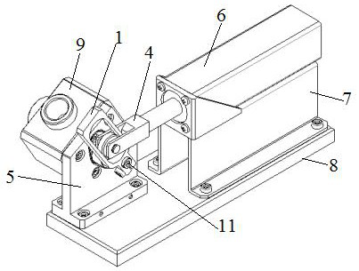
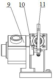
[0039] A gas alternator, such as Figure 1-Figure 5As shown, it includes a driving mechanism, a generator casing 9, and a rotating cylinder 11, the rotating cylinder 11 is installed in the generator casing 9, and one end extends out of the generator casing 9 and is connected with the connecting part. The mechanism is connected with the connecting part and drives the rotating cylinder 11 to rotate; the side wall of the rotating cylinder 11 is provided with a gray ring 14 and an O-ring 13 along the circumferential direction, and the tail end of the rotating cylinder 11 is provided with a rotating cylinder A shaft sleeve 15, and the head end is connected to the connecting part; the outer side of the generator is provided with a rotating drum fixing seat 10 that is limitedly connected with the rotating drum 11, and a stopper is arranged between the rotating drum fixing seat 10 and the rotating drum 11. Push the needle roller bearing 12, the connecting part passes through the drum ...

Embodiment 2

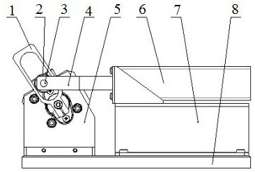
[0044] This embodiment is optimized on the basis of embodiment 1, such as Figure 1-Figure 4 As shown, the drive mechanism includes an electric cylinder 6, a push rod 4, a swing rod 1, and an angular contact ball bearing 2. The drive end of the electric cylinder 6 is provided with a push rod 4, and the free end of the push rod 4 is provided with a The installation groove; the swing rod 1 is connected with the installation groove through the rotating pin 3 sleeved with the angular contact ball bearing 2, the swing rod 1 is provided with a hollow cavity, and the angular contact ball bearing 2 is arranged in the hollow cavity; The bottom of the swing rod 1 is connected with the connecting part.

[0045] The free end of the push rod 4 of the electric cylinder 6 looks like a "channel steel". Put the swing rod 1 connected to the drum 11 into the groove, and connect it through the rotating pin 3 covered with the angular contact ball bearing 2. The upper part of the swing rod 1 is Ho...

Embodiment 3

[0053] This embodiment is optimized on the basis of Embodiment 1 or 2. The generator casing 9 is provided with an installation chamber inside, and the rotating drum 11 is rotatably installed in the installation chamber, and the installation chamber is correspondingly provided with an air inlet. , Exhaust port, air pressure output port.

[0054] Further, the connection part is a rod-shaped structure, preferably the connection part can be set as a slender rod structure.

[0055] Other parts of this embodiment are the same as those of Embodiment 1 or 2 above, so details are not repeated here.


PUM


Abstract

The invention discloses a gas alternating generator which comprises a driving mechanism, a generator shell and a rotary drum, the rotary drum is rotationally installed in the generator shell, one end of the rotary drum extends out of the generator shell and is connected with a connecting part, and the driving mechanism is connected with the connecting part and drives the rotary drum to rotate; a Glyd ring and an O-shaped ring are arranged on the side wall of the rotary drum in a sleeving manner in the circumferential direction, and a rotary drum shaft sleeve is arranged at the tail end of the rotary drum in a sleeving manner; the outer side of the generator is provided with a rotating drum fixing seat which is connected with the rotating drum in a limiting manner, a thrust needle bearing is arranged between the rotating drum fixing seat and the rotating drum, and the connecting part penetrates through the rotating drum fixing seat and is connected with the driving mechanism; and the generator shell and the rotary drum are correspondingly provided with an air inlet, an air outlet and an air pressure output port respectively. The problems that an existing alternating generator is poor in reliability, noise pollution is likely to be caused, the testing form is fixed and single, and the control precision is poor are effectively solved, and the good practicability is achieved.

Description

technical field [0001] The invention belongs to the technical field of gas alternating pressure testing equipment, and in particular relates to a gas alternating generator. Background technique [0002] The gas alternating pressure test is an important test method for testing the fatigue limit of many products in the aviation field, especially components such as pressure sensors, signal devices, and pressure gauges. The method of gas alternating pressure test is to simulate the actual working conditions of these components, such as simulating the pressure change of the circulating medium in the actual working conditions. [0003] The function of the traditional alternating pressure test is relatively single, and generally it can only simulate a simple fixed waveform, so it cannot accurately determine the ultimate service life of the sample to be tested. With the development of aviation technology, in order to adapt to the complex aviation environment, various main engine ma...

Claims


Application Information

Patent Timeline
Patent Type & Authority Applications(China)
IPC IPC(8): F16K5/04F16K5/08F16K27/06F16K31/04
CPCF16K5/0407F16K5/0442F16K5/045F16K5/0478F16K5/08F16K27/065F16K31/043
Inventor 李永杰高涛
Owner CHENGDU KAITIAN ELECTRONICS
Why Eureka
Try Eureka