
Ballast Tank Structure with Connecting Piping

A technology for connecting pipelines and ballast tanks, which is applied in the direction of partial cabins, hulls, and ship construction in the hull. It can solve problems such as insufficient utilization of tank capacity, and achieve the goal of ensuring tank capacity utilization, improving energy efficiency, and reducing fuel consumption. Effect

Active Publication Date: 2021-10-01
JIANGNAN SHIPYARD GRP CO LTD
View PDF7 Cites 0 Cited by
  • Summary
  • Abstract
  • Description
  • Claims
  • Application Information

AI Technical Summary

Problems solved by technology

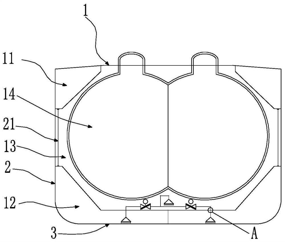
[0004] In order to solve the above-mentioned technical problems, the present invention provides a ballast tank structure with connecting pipelines, which is a more efficient and safer ballast tank structure for liquefied gas ships, to solve the problems of the existing ballast tank design. Technical issues with insufficient capacity utilization

Method used


Image

  • Ballast Tank Structure with Connecting Piping
  • Ballast Tank Structure with Connecting Piping
  • Ballast Tank Structure with Connecting Piping

Examples


Embodiment Construction

[0021] The specific implementation manners of the present invention will be described in further detail below in conjunction with the accompanying drawings. These embodiments are only used to illustrate the present invention, not to limit the present invention.

[0022] In the description of the present invention, it should be noted that the terms "center", "longitudinal", "transverse", "upper", "lower", "front", "rear", "left", "right", " The orientations or positional relationships indicated by "vertical", "horizontal", "top", "bottom", "inner" and "outer" are based on the orientations or positional relationships shown in the drawings, and are only for the convenience of describing the present invention and Simplified descriptions, rather than indicating or implying that the device or element referred to must have a particular orientation, be constructed and operate in a particular orientation, and thus should not be construed as limiting the invention. In addition, the ter...


PUM


Abstract

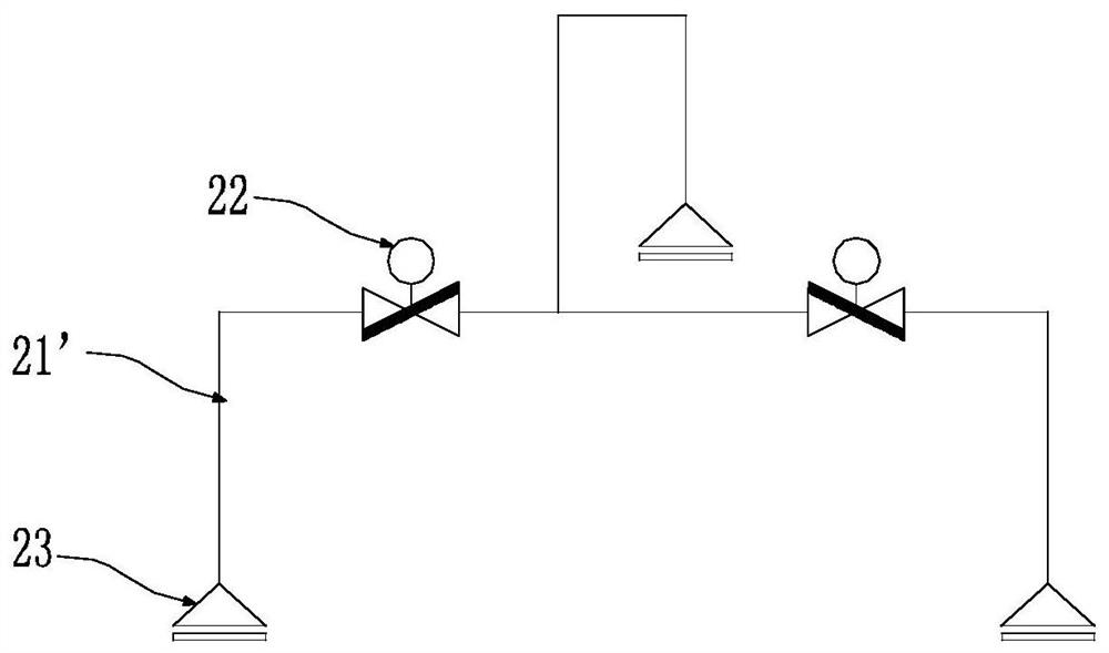
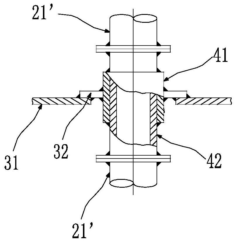
The invention belongs to a ballast tank structure with connecting pipelines in the field of ship layout in the field of shipbuilding. The water tanks are arranged between the hull shell and the bottom of the ship, adjacent to the cargo tanks; the top ballast tanks and the bottom ballast tanks are symmetrically arranged on both sides of the ship; the top ballast tanks and the bottom ballast tanks on the same side The tanks are airtightly connected through the first communication pipeline, suction ports are arranged in the bottom ballast water tanks and cargo tanks on both sides, and pressure control valves are arranged in the cargo tanks; the pressure control valves and suction ports are sealed through the second communication pipeline connected. The design of the ballast tank structure reduces the main dimension requirements of the ship with the same tank capacity, improves the energy efficiency of the ship, reduces the fuel consumption of the ship, and reduces the operating cost of the ship owner.

Description

technical field [0001] The invention relates to the field of ship layout in the field of ship manufacturing, and more specifically relates to a ballast tank structure. Background technique [0002] At present, the world's gas energy consumption and demand for gas chemical raw materials continue to rise, which brings great opportunities for the development of liquefied gas carriers (referred to as liquefied gas carriers). Under this international situation, all ship design units have increased their efforts in the research and development of liquefied gas carriers. [0003] In the process of designing and producing liquefied gas carriers, the damage stability and safety of the cargo hold area is the top priority. In order to improve the damage stability of ships, the double-hull design scheme of the ballast tank in the cargo hold area is often adopted, and the double-hull width in the usual double-hull arrangement of the ballast tank needs to be greater than one-fifth of the...

Claims


Application Information

Patent Timeline
Patent Type & Authority Patents(China)
IPC IPC(8): B63B25/12B63B11/04B63B43/06
CPCB63B11/04B63B25/12B63B43/06
Inventor 王璐玭柳卫东樊涛
Owner JIANGNAN SHIPYARD GRP CO LTD
Learn More