
ironing rack

An ironing rack and frame technology, applied in the field of ironing racks, can solve the problems of inability to iron clothes, damage clothes, consume a lot of time, etc., and achieve the effects of improving aesthetic sense, easy storage, and easy folding

Active Publication Date: 2022-07-22
博得生活株式会社
View PDF9 Cites 0 Cited by
  • Summary
  • Abstract
  • Description
  • Claims
  • Application Information

AI Technical Summary

Problems solved by technology

[0004] But requires a fastening unit for tensioning the garment, whereby garments of certain materials may be damaged
[0005] Moreover, in the case of conventional vertical steam irons, the mechanism for hanging clothes is a simple triangular clothes hanger-shaped clothes hanging part. Therefore, the clothes to be ironed cannot be completely fixed and need to be pulled one by one with one hand Stretch is applied to iron clothes in a vertical position
[0006] Moreover, in the conventional vertical steam iron with a clothes unfolding device that can be unfolded to the left and right, due to the structure that protrudes to both sides by a certain length based on the central support rod when the left and right width of the hanger is completely folded at the minimum size Due to the limitations of the above, not only can not iron the clothes smaller than the minimum size on the ironing iron, but also when viewed from the front, it always protrudes to the left and right, which has the problems of poor aesthetic feeling and difficult storage
[0007] And, in the conventional vertical ironing stand, there is the trouble of having to do the following repeated actions, that is, clothes such as a coat are taken off from a general triangular hanger and put on the ironing stand, and after ironing, Take it off again and hang it on the original hanger
[0008] And, there is the trouble that power or other additional devices are needed in order to maintain the tight state of the clothes in the prior art
That is, when the clothes are stretched out tightly, the user needs to perform a plurality of steps, so there is a problem that a lot of time is consumed when the clothes are stretched out tightly

Method used


Image

  • ironing rack
  • ironing rack
  • ironing rack

Examples


Embodiment Construction

[0035] Terms used in this specification are briefly explained, and the present invention is explained in detail.

[0036] The terms used in the present invention are generally selected as far as possible considering functions in the present invention, but may be changed according to the intention of those of ordinary skill in the art or precedents, the appearance of new technologies, and the like. Therefore, the terms used in the present invention should not be defined on the basis of simple term names, but should be defined on the basis of the meanings the terms have and the overall content of the present invention.

[0037] Throughout the specification, when it is stated that a part "includes" a structural element, unless there is a special description, it means that other structural elements are also included, rather than excluding other structural elements.

[0038] The following describes the embodiments of the present invention in detail with reference to the accompanyin...


PUM


Abstract

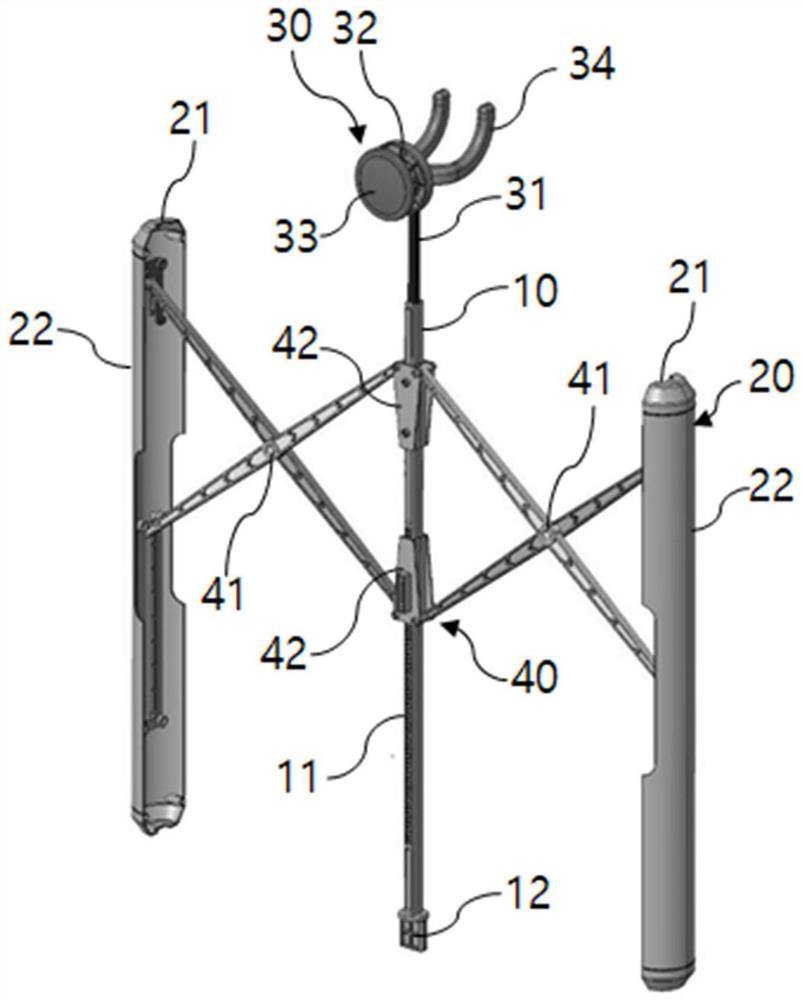
The present invention relates to an ironing rack, in more detail, comprising: a frame formed to be elongated in a longitudinal direction; a clothes expansion part, which expands in both directions on the basis of the frame to expand the clothes; a clothes hanger hanging part, a hanger provided on the upper side of the frame for hanging the clothes; and a transfer portion formed so as to surround the outer peripheral surface of the frame to expand or fix the clothes expansion portion, the frame including a length along the length The concave-convex portion is formed in a long direction and has a continuously formed groove, the transfer portion includes a fixing portion for selectively fixing the clothing expansion portion, the fixing portion is formed in the shape of a curved wire, and the curved portion of the fixing portion is inserted into the fixing portion. The grooves of the concave-convex part fix the clothing expansion part, and when the user exerts external force, the curved part of the fixing part can be separated from the groove of the concave-convex part to expand or fold the clothing expansion part.

Description

technical field [0001] The present invention relates to an ironing rack, and more particularly, to an ironing rack capable of unfolding clothes in such a manner that the clothes can be ironed in a state where the clothes are hung on the clothes rack. Background technique [0002] In order to iron clothes more conveniently and quickly, there is an increasing demand for vertical ironing racks that can hang clothes on a hanger for ironing. [0003] With reference to the related art, as shown in Korean Patent Publication No. 10-2009-0104342, there is disclosed a steam ironing rack, which is used to tighten the upper, lower, left, and right sides of the upper, lower, left and right sides to be ironed. In the hanging state, the wrinkled part can be ironed by a steam iron, so the ironing efficiency is high and the ironing time is effectively shortened. [0004] However, a fixing unit for tightening the clothes is required, whereby the clothes of certain materials may be damaged. ...

Claims


Application Information

Patent Timeline
Patent Type & Authority Patents(China)
IPC IPC(8): D06F73/00
CPCD06F73/00D06F87/00
Inventor 李相勋
Owner 博得生活株式会社
Learn More