Pre-cleaning device

A technology of pre-cleaning and pressurizing device, which is applied in the manufacturing of electrical components, circuits, semiconductor/solid-state devices, etc., can solve the problem that the pre-cleaning device can no longer meet the requirements of the process.

Pending Publication Date: 2020-07-17
INST OF MICROELECTRONICS CHINESE ACAD OF SCI +1
View PDF5 Cites 2 Cited by
  • Summary
  • Abstract
  • Description
  • Claims
  • Application Information

AI Technical Summary

Problems solved by technology

In this context, the use of figure 1 and figure 2 The shown prior art pre-cleaning unit is no longer adequate for the process

Method used


Image

  • Pre-cleaning device
  • Pre-cleaning device
  • Pre-cleaning device

Examples


Embodiment Construction

[0026] In order to make the purpose, technical solutions and advantages of the embodiments of the present invention clearer, the technical solutions in the embodiments of the present invention will be clearly and completely described below in conjunction with the drawings in the embodiments of the present invention. Obviously, the described embodiments It is only some embodiments of the present invention, but not all embodiments. Based on the embodiments of the present invention, all other embodiments obtained by persons of ordinary skill in the art without making creative efforts belong to the protection scope of the present invention.

[0027] In order to facilitate the understanding of the pre-cleaning device provided by the embodiment of the present invention, the application scene of the pre-cleaning device provided by the embodiment of the present invention is firstly described below. Polishing and cleaning are performed to remove particles on the surface of the wafer in...


PUM


Abstract

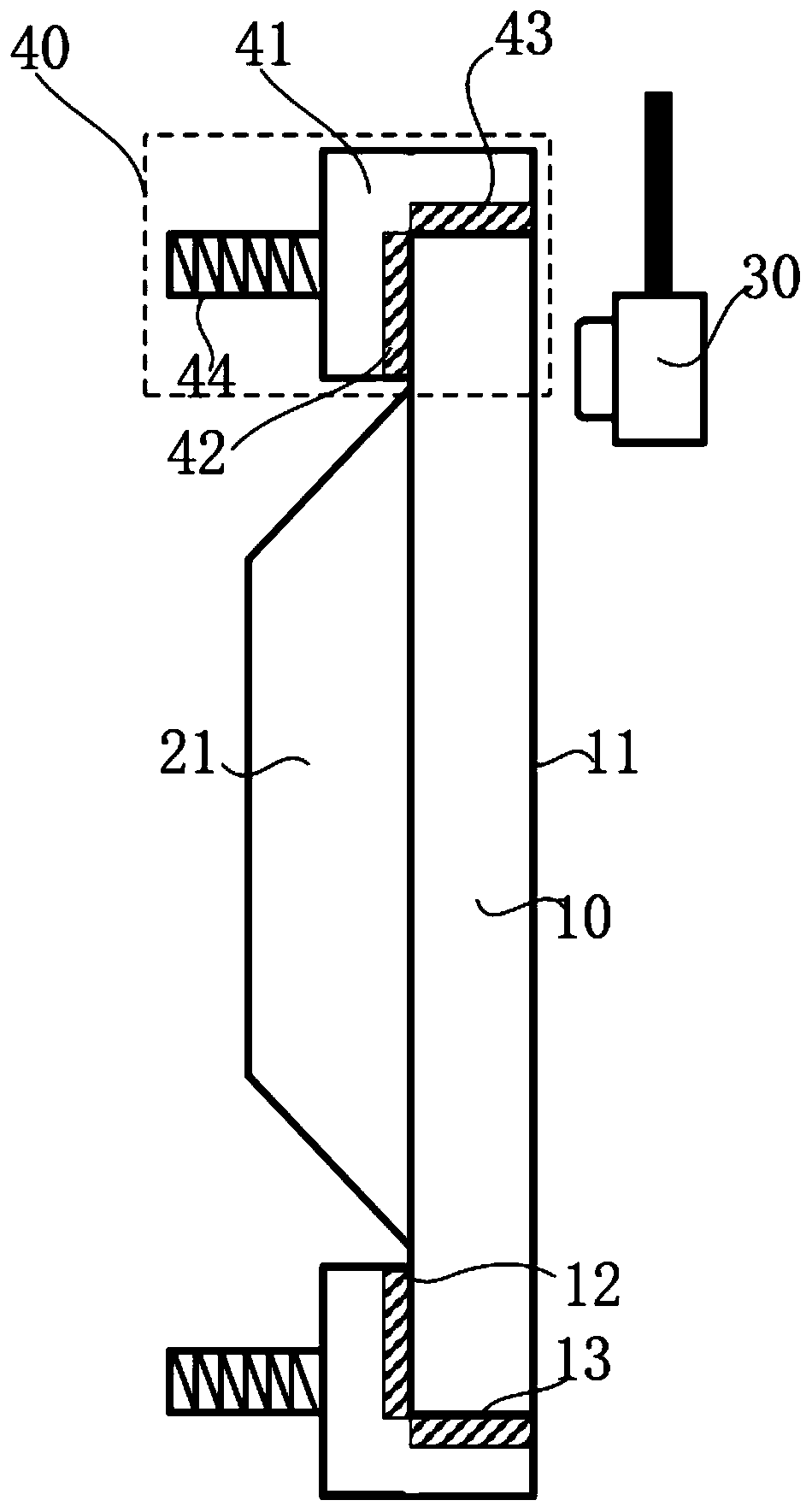
The invention provides a pre-cleaning device which is used for removing particles on the surface of a wafer and comprises a supporting structure, a clamping assembly assembled on the supporting structure and a first polishing assembly arranged on the supporting structure and used for polishing the first surface of the wafer. The clamping assembly comprises a sucker used for adsorbing the second surface of the wafer and driving the wafer to rotate around a fixed point, and the area of the second surface of the wafer is larger than that of the sucker. And the second polishing assembly is arranged on the supporting structure and is used for polishing the surface, which is not covered by the sucker of the second surface of the wafer and the edge surface. The second polishing assembly is used for polishing the surface, not covered by the suction cup, of the second face of the wafer and the edge face of the wafer. Particles on the back surface and the edge surface of the wafer can be removedmore effectively, so that the content of the particles on the back surface and the edge surface of the wafer is reduced, the local out-of-focus phenomenon in the subsequent photoetching process of the wafer is improved, and the production yield and the production efficiency of semiconductor devices are improved.

Description

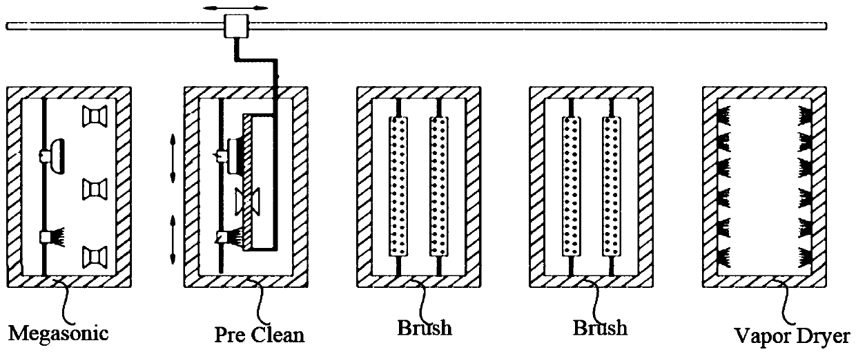
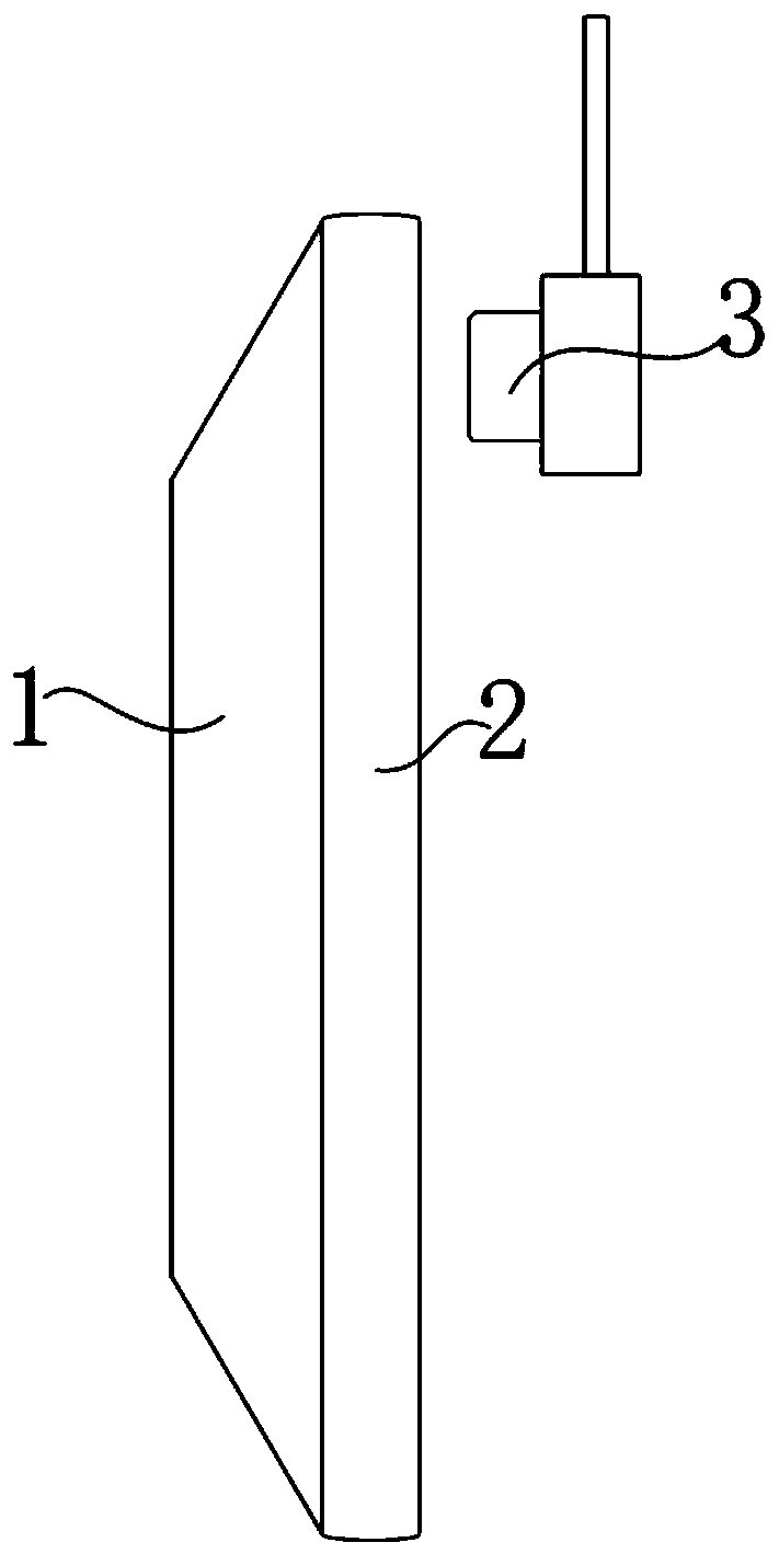
technical field [0001] The invention relates to the technical field of semiconductor manufacturing, in particular to a pre-cleaning device. Background technique [0002] At present, the existing CMP cleaning equipment (CMP Cleaner, where CMP is the abbreviation of Chemical MechanicalPolishing, which means chemical mechanical polishing) is mainly used to remove the particles on the wafer (Wafer), and to clean the wafer after particle removal. Dry Clean. Its working steps are as follows figure 1 As shown, the main sequence includes: Megasonic cleaning → Pre Clean → BrushBrush → Vapor Dryer. The pre-cleaning device in the prior art is such as figure 2 In the shown structure, the vacuum chuck 1 absorbs the wafer 2 and drives the wafer 2 to rotate, and the polishing assembly 3 cleans the wafer front (waferfront) of the wafer 2 . [0003] In the past, with the above process, there was no local defocus phenomenon caused by particles generated in the semiconductor process. ...

Claims


Application Information

Patent Timeline
IPC IPC(8): H01L21/02H01L21/306H01L21/67
CPCH01L21/02057H01L21/30625H01L21/67023Y02P70/50
Inventor 鲁荣硕张月杨涛卢一泓刘青
Owner INST OF MICROELECTRONICS CHINESE ACAD OF SCI
Why Eureka
Try Eureka