Communication method, communication device and storage medium
A communication method and a technology of a communication device, which are applied in wireless communication, signaling distribution, transmission path sub-channel distribution, etc., can solve problems such as receiving errors and inconsistencies in understanding terminal equipment, and achieve the effect of low receiving complexity
Active Publication Date: 2020-07-17
HUAWEI TECH CO LTD
19 Cites 3 Cited by
AI-Extracted Technical Summary
Problems solved by technology
However, if the terminal device fails to detect the DCI that triggers A-CSI, the network device's understanding of the uplink c...
Method used
[0105] In order to solve this problem, the embodiment of the present application provides a communication method, by allocating different uplink control channel resources for feedback information such as ACK/NACK and uplink information including A-CSI, so that the network device can correctly receive the terminal The uplink information sent by the device does not require multiple blind detections, reducing the complexity of receiving.
[0114] Optionally, in an embodiment of the present application, the method further includes: after receiving the first DCI, the terminal device also receives one or more DCIs from the network device, and the one or more Multiple DCIs are used to instruct the terminal device to jointly send the feedback information corresponding to the DCI and the A-CSI report corresponding to the A-CSI. By repeatedly instructing the terminal device to send the A-CSI report, the success rate of the terminal device sending the A-CSI is improved.
[0168] In this embodiment, high-level configuration or pre-definition of the above-mentioned first group of resource sets and second group of resource sets is adopted, which has high efficiency and has little impact on the communication process between the terminal device and the network device.
[0267] In addition to silencing one of the above-mentioned uplink control channels or uplink data channels overlapping in the time domain according to the priority to avoid network equipment receiving errors, in another embodiment of the present application, the terminal equipment can also select from different DCI Respectively acquire indication information instructing the terminal device to sen...
Abstract
The invention provides a communication method, a communication device and a storage medium. The method comprises the steps that terminal equipment determines uplink information; when the uplink information is first feedback information, the terminal equipment determines a first uplink control channel resource corresponding to the first feedback information and sends the first feedback informationon the first uplink control channel resource; when the uplink information comprises aperiodic channel state information (A-CSI); and the terminal equipment determines a second uplink control channel resource corresponding to the uplink information and sends the uplink information on the second uplink control channel resource, wherein the first uplink control channel resource is different from thesecond uplink control channel resource, so that the network equipment identifies whether the uplink information contains the A-CSI or not through the control channel resource used by the received uplink information, the uplink information can be correctly received, multiple times of blind detection are not needed, and the receiving complexity is low.
Application Domain
Signal allocationPayload allocation +1
Technology Topic
Real-time computingControl channel +4
Image
Examples
- Experimental program(1)
Example Embodiment
[0073] The technology described in the embodiments of this application can be used in a variety of communication systems, such as long term evolution (LTE) systems, new radio (NR) systems, and evolved LTE (evolved LTE, eLTE) systems and other 5G (the fifth generation (fifth generation) system, or other next generation (NG) communication systems.
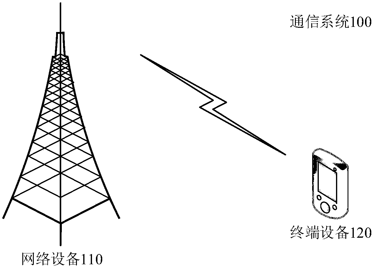
[0074] figure 1 It is a schematic diagram of a communication system 100 provided by an embodiment of the present application.
[0075] Such as figure 1 As shown, the communication system 100 includes a network device 110 and a terminal device 120. The terminal device 120 communicates with the network device 110 through electromagnetic waves. When the terminal device 120 sends information, the wireless communication module of the terminal device 120 can obtain information bits to be sent to the network device 110 through the channel. These information bits are, for example, generated by the processing module of the terminal device, received from other devices, or in the terminal. Information bits stored in the storage module of the device. Specifically, the terminal device 120 can be used as an entity that sends uplink data to transmit an uplink channel to the network device 110 (the uplink channel can carry uplink data). Of course, the terminal device 120 can also receive the network device 110 directly or through a network such as a relay device. Downlink data forwarded by the node.
[0076] In this application, the terminal device 120 may be various devices that provide users with voice and/or data connectivity, such as a handheld device with a wireless connection function, or a processing device connected to a wireless modem. The terminal device 120 may communicate with a core network via an access network, such as a radio access network (RAN), and exchange voice and/or data with the RAN. The terminal device 120 may include user equipment (user equipment, terminal equipment), wireless terminal equipment, mobile terminal equipment, subscriber unit (subscriber unit), subscriber station (subscriber station), mobile station (mobile station), mobile station (mobile), Remote station (remote station), access point (access point, AP), remote terminal equipment (remote terminal), access terminal equipment (accessterminal), user terminal equipment (user terminal), user agent (user agent), or user Equipment (userdevice) and so on. For example, it may include mobile phones (or "cellular" phones), computers with mobile terminal devices, portable, pocket-sized, handheld, computer-built or vehicle-mounted mobile devices, smart wearable devices, and so on. For example, personal communication service (PCS) phones, cordless phones, session initiation protocol (SIP) phones, wireless local loop (wireless local loop, WLL) stations, personal digital assistants, PDA), smart bracelets, smart watches and other equipment. It also includes restricted devices, such as devices with low power consumption, or devices with limited storage capabilities, or devices with limited computing capabilities. Examples include barcodes, radio frequency identification (radio freq terminal equipment ncy identification, RFID), sensors, global positioning system (GPS), laser scanners and other information sensing devices. In addition, the terminal device 120 may also be a drone device. In the embodiments of the present application, the chips applied in the above-mentioned devices may also be referred to as terminal devices.
[0077] In this application, the network device 110 may be an access network device, and the access network device may be used to connect the terminal device 110 to an access network such as a RAN. The network equipment 110 may be a base station defined by the 3rd generation partnership project (3rd generation partnership project, 3GPP), for example, it may be a base station equipment in an LTE system, that is, an evolved NodeB (evolved NodeB, eNB/eNodeB); or It is the access network side equipment in the NR system, including gNB, transmission point (trasmission point, TRP), home base station (for example, home evolved Node B, or home Node B, HNB), base band unit (BBU), Or an access network device consisting of a centralized unit (CU) and a distributed unit (DU). Among them, the CU can also be called a control unit (control unit), which uses the CU-DU structure to change the protocol of the base station The layers are separated, part of the protocol layer functions are placed under the centralized control of the CU, and some or all of the protocol layer functions are distributed in the DU, and the CU is centrally controlled by the DU. In addition, when the eNB is connected to a 5G core network (5G-Core, 5G CN), the LTE eNB may also be called an eLTE eNB. Specifically, the eLTE eNB is an evolved LTE base station equipment based on the LTE eNB, and can be directly connected to the 5G CN. The eLTE eNB also belongs to the base station equipment in the NR. The network device 110 may also be a wireless terminal (WT), such as an access point (AP) or an access controller (AC), or another network capable of communicating with a terminal and a core network. Devices, such as relay devices, vehicle-mounted devices, smart wearable devices, etc. The embodiments of the present application do not limit the types of network devices.
[0078] The communication system 100 is only an example, and the communication system applicable to the present application is not limited to this. For example, the number of network devices and terminal devices included in the communication system 100 is only an example, and the communication system 100 may include more than one terminal device and Internet equipment. A network device can manage one or more terminal devices, that is, one or more terminal devices can access the network through the same network device. In addition, the communication system 100 may also include other devices. For example, it may also include a wireless relay device and a wireless backhaul device. figure 1 Do not make a gesture.
[0079] The embodiment of this application defines the one-way communication link from the access network to the terminal as the downlink, the data transmitted on the downlink is the downlink data, and the transmission direction of the downlink data is called the downlink direction; and the one from the terminal to the access network The unidirectional communication link is the uplink, the data transmitted on the uplink is the uplink data, and the transmission direction of the uplink data is called the uplink direction.
[0080] The resources described in the embodiments of the present application may also be referred to as transmission resources, including one or more of time domain resources, frequency domain resources, and code channel resources, which can be used to carry data in an uplink communication process or a downlink communication process Or signaling.
[0081] The time unit mentioned in the embodiment of the present application refers to a unit of time domain resources used for wireless communication between a network device and a terminal device. A period of time domain resources can be divided into multiple time units. Moreover, in the present application, multiple time units may be continuous or non-continuous, that is, there are preset time intervals between some adjacent time units. This application does not limit the length of a time unit. For example, a time unit may be one or more subframes (subframe); or, it may also be one or more time slots (slot); or, it may also be one or more symbols (symbol). The symbols are also called time-domain symbols, and the time-domain symbols can be orthogonal frequency division multiplexing (OFDM) symbols, or single carrier frequency division multiple access (SC-FDMA). symbol.
[0082] The codebook described in the embodiment of the present application includes a set of ACK/NACK corresponding to downlink data that is fed back on the uplink time unit. Wherein, the downlink data transmission corresponding to ACK/NACK is directly scheduled by DCI or sent in a preset pattern after being activated by a DCI. Therefore, ACK/NACK can be considered to be triggered by DCI, which can also indicate/trigger terminal equipment Feedback A-CSI, the terminal device can send the codebook and the A-CSI to the network device at the same time in the same uplink time unit, or send the codebook and the A-CSI to the network device in different uplink time units. A-CSI. The codebook in the embodiment of the present application includes a dynamic codebook and a semi-static codebook. It can be understood that the codebook may also contain other uplink information, which is not limited.
[0083] Among them, the dynamic codebook is also called Type 2 (Type 2) codebook. The terminal device can detect the PDCCH at each PDCCH monitoring occasion (monitoring occasion), and obtain downlink control information (DCI), according to the time domain resource allocation (time domain resource allocation) field and PDSCH-to-HARQ- The timing field determines the ACK/NACK feedback time slot corresponding to the PDSCH scheduled by the PDCCH. The terminal device first determines the slot number of the PDSCH according to the slot number of the PDCCH and the slot offset value (K0) from the PDCCH to the PDSCH contained in the time domain resource allocation field, and then obtains the timing offset according to the PDSCH-to-HARQ-timing field. Shift (K1), that is, the offset value from the PDSCH slot to the feedback slot corresponding to the PDSCH, so as to determine in which slot the ACK/NACK is sent. For an uplink time slot, the terminal device can only feed back the actually scheduled ACK/NACK that points to the time slot. Because the base station schedules data and triggers the ACK/NACK, it will point the ACK/NACK to the downlink data in the same uplink time slot. Count, where the value of the counter can be represented by the downlink assignment index (downlink assignment index, DAI), and the DAI is included in the DCI. Therefore, the UE can determine whether it has missed detection according to the DAI in the received PDCCH A certain DCI makes the codebook size of the feedback ACK/NACK correct.
[0084] Semi-static codebook is also called Type 1 (Type 1) codebook. The network equipment configures the K1 set (K1set) and the time domain resource allocation table for the terminal equipment through protocol pre-defined or high-level signaling. The terminal equipment determines the candidate time domain position of the PDSCH according to the time domain resource allocation table, and according to the candidate time domain position of the PDSCH Set with K1 to determine the time slot where the PDSCH feedback information may be located. In each uplink time slot, the terminal equipment determines the downlink PDSCH timing set associated with the uplink time slot according to the PDSCH candidate time domain position and the K1 set, that is, the associated downlink time slot and the PDSCH timing set in the downlink time slot, and then according to the association The codebook is generated by the collection of downlink PDSCH occasions. That is to say, for an uplink time slot, the size of the feedback semi-static codebook is fixed, and it can include all ACK/NACKs that may be directed to the downlink data transmission of the time slot.
[0085] It can be understood that the above description of the dynamic codebook and the semi-static codebook takes the time unit as the time slot as an example, which does not constitute any limitation to this application.
[0086] The uplink control channel resource set described in the embodiment of the present application includes one or more uplink control channel resources. The upper control channel is PUCCH as an example. At present, K (1≤K≤4) PUCCH resource sets are configured in the NR system, and the kth PUCCH resource set (k=0, or, 1, or 2, Or, 3) N for the payload size of the ACK/NACK carried UCI The value range is N k ≤N UCI k+1 , Where N UCI Indicates the number of bits of UCI, and N is a positive integer. The current NR system stipulates N 0 =1&N 1 =3&N 4 = 1706. In other words, the load size of ACK/NACK can also be characterized by the number of UCI bits. The group of uplink control channel resource sets described in the embodiments of the present application may also be referred to as an uplink control channel resource group (resource set group). An uplink control channel resource group may include one or more uplink control channel resource sets. The one or more uplink control channel resource sets may be defined in an existing protocol, or may be newly defined in this application, and are not limited.
[0087] It should be understood that the term "and/or" in this text is only an association relationship describing the associated objects, which means that there can be three relationships, for example, A and/or B can mean that there is A alone, and both A and B exist. , There are three cases of B alone. In addition, the character "/" in this text indicates that the associated objects before and after are in an "or" relationship.
[0088] It should be understood that in the embodiment of the present invention, "B corresponding to A" means that B is associated with A. In one implementation, B can be determined according to A. However, it should also be understood that determining B based on A does not mean that B is determined only based on A, and B can also be determined based on A and/or other information. The "plurality" in the embodiments of the present application refers to two or more.
[0089] The descriptions of the first, second, third, etc. appearing in the embodiments of this application are only used to illustrate and distinguish the description objects. There is no order, and it does not mean that there is a special limitation on the amount of information in the embodiments of this application, and cannot constitute Any limitations on the embodiments of this application.
[0090] The "connection" appearing in the embodiments of this application refers to various connection modes such as direct connection or indirect connection to realize communication between devices, which is not limited in the embodiment of this application.
[0091] Unless otherwise specified, "transmit/transmission" in the embodiments of this application refers to two-way transmission, including sending and/or receiving actions. Specifically, the "transmission" in the embodiment of the present application includes the sending of data, the receiving of data, or the sending of data and the receiving of data. In other words, the data transmission here includes uplink and/or downlink data transmission. Data may include channels and/or signals. Uplink data transmission means uplink channel and/or uplink signal transmission, and downlink data transmission means downlink channel and/or downlink signal transmission.
[0092] The services appearing in the embodiments of the present application refer to communication services obtained by the terminal from the network side, including control plane services and/or data plane services, such as voice services, data traffic services, and so on. The sending or receiving of services includes the sending or receiving of service-related data (data) or signaling (signaling).
[0093] The "network" and "system" appearing in the embodiments of the present application express the same concept, and the communication system is the communication network.
[0094] In this application, the use of a singular element is intended to mean "one or more", but not only "one and only one", unless otherwise specified. "Some" can refer to one or more.
[0095] Hereinafter, the communication system 100 is an NR system as an example for description.
[0096] During the communication process between the terminal device 120 and the network device 110, the terminal device 120 can perform CSI measurement and feed back the measurement result to the network device 110, so that the network device 110 can improve the communication link performance by adjusting the transmitted signal strength, etc., thereby improving Reliability of service transmission.
[0097] A-CSI feedback is a type of CSI feedback. When a service arrives, A-CSI feedback can be triggered by DCI triggering or implicit triggering to assist in improving the quality of subsequent data transmission. The A-CSI feedback can be carried on an uplink data channel, such as PUSCH, and can also be carried on an uplink control channel, such as a physical uplink control channel (PUCCH). A possible implementation method is to simultaneously trigger the terminal equipment to feed back A-CSI on the short-format uplink control channel (short PUCCH, sPUCCH) by scheduling the DCI of the downlink data, which can reduce the DCI overhead and realize the fast A-CSI feedback.
[0098] For A-CSI feedback on sPUCCH, if the PUCCH resource carrying A-CSI and the PUCCH resource carrying ACK/NACK (hereinafter referred to as "A/N") overlap in the time domain, then A-CSI and A/N Joint feedback is possible. Specifically, the terminal device 120 may jointly code A-CSI and A/N, and select the PUCCH resource to carry the aforementioned A-CSI and A/N according to the ARI in the last DCI received.
[0099] The joint feedback of A-CSI and A/N mentioned in this application may refer to the joint feedback (or called joint transmission) of A-CSI corresponding to the downlink data scheduled by the DCI that triggers the A-CSI; It may also refer to the joint feedback of A/N corresponding to the downlink data scheduled by the A-CSI and other DCI, which is not limited.
[0100] Figure 2(a) is an example of joint feedback between A-CSI and A/N in the joint feedback mode. In the joint feedback mode, since the DCI that triggers A-CSI also schedules downlink data, if the terminal device 120 feeds back A/N for the downlink data, the A-CSI can be in the same time slot and the same PUCCH as the A/N. Joint feedback on resources. As shown in Figure 2(a), DCI1 schedules downlink data in uplink time slot 0 (slot 0), and the value of 01 in the CSI Request field in DCI indicates that an A-CSI feedback on sPUCCH is triggered. At the same time, through The value of the PDSCH-to-HARQ-ACK-Timing field K1 in DCI 1 is 2, indicating that the first A/N and A-CSI corresponding to the downlink data are fed back jointly in the uplink slot 2 and in the uplink In slot 1 (slot 1), DCI 2 schedules downlink data, but does not trigger A-CSI. The value of K1 in the PDSCH-to-HARQ-ACK-Timing field in DCI 2 indicates that the downlink data scheduled by DCI 2 corresponds to The second A/N is fed back in slot 2. Therefore, in the scenario of FIG. 2(a), A-CSI is fed back jointly with the first A/N and the second A/N.
[0101] Figure 2(b) is an example of joint feedback of A-CSI and A/N in the single feedback mode. In the separate feedback mode, although the DCI that triggered the A-CSI itself also schedules downlink data, the terminal device 120 feeds back the DCI-triggered A-CSI corresponding to the downlink data in different time slots or different PUCCH resources in the same time slot. The network device 110 indicates the time slot and/or PUCCH resource for A-CSI feedback to the terminal device 120. As shown in Figure 2(b), DCI 1 schedules downlink data in slot 0 and the value of 01 in the CSI Request field in DCI1 indicates that an A-CSI feedback on sPUCCH is triggered. At the same time, through the PDSCH-to in DCI 1 -The value of the HARQ-ACK-Timing field K1 is 1, indicating that the first A/N corresponding to the downlink data is fed back in the uplink slot 1, and the value of the Timing field Y of the A-CSI is 2 to indicate that the A-CSI is in the uplink slot 2. Feedback. In slot 1, DCI 2 schedules downlink data without triggering A-CSI. The value 1 of the PDSCH-to-HARQ-ACK-Timing field K1 in DCI 2 indicates the second A corresponding to the downlink data scheduled by DCI 2. /N feedback in slot 2. Therefore, in the scenario of FIG. 2(b), the A-CSI and the first A/N are fed back separately, and the A-CSI and the second A/N are fed back together.
[0102] It can be understood that the above-mentioned joint feedback mode and separate feedback mode are distinguished by whether the A-CSI is fed back with the A/N indicated by the DCI that triggers the A-CSI. In the single feedback mode, A-CSI can be distinguished from other DCIs. The indicated A/N overlap, thereby performing joint feedback.
[0103] The "overlap in the time domain" or "overlap" mentioned in the embodiments of this application may mean that the time units occupied in the time domain overlap, including full overlap or partial overlap. The time unit may be a symbol or a time slot. . For example, in scenario 2(a), A-CSI and the first A/N and the second A/N can be fed back in the same time slot, and the occupied time slots overlap, even if the three occupy the same time slot. Different symbols still belong to the category of "overlap in the time domain" described in the embodiments of this application; in scenario 2(b), the symbols occupied by A-CSI and the second A/N overlap, which belong to the embodiments of this application The category of "overlapping in time domain".
[0104] For any of the above scenarios, if the terminal device 120 misses DCI 1, it will be considered that only A/N needs to be fed back in slot 2, and there is no need to feed back A-CSI. Then the terminal device 120 only feeds back A/N, but the network device 110 still receives A/N according to the rule that the terminal device 120 feeds back A/N and A-CSI at the same time, which will cause the A/N reception to fail.
[0105] In order to solve this problem, the embodiment of the present application provides a communication method, which allocates different uplink control channel resources for feedback information such as ACK/NACK and uplink information containing A-CSI, so that the network device can correctly receive the data sent by the terminal device. Uplink information does not require multiple blind checks, reducing the complexity of receiving.
[0106] For ease of description, the communication method shown in the embodiment of the present application is described by taking terminal equipment and network equipment as the execution subject as an example. It can be understood that the execution subject of the communication method described in the embodiment of the present application may also be other communication devices. For example, the chip will not be explained below.
[0107] image 3 It is a schematic flowchart of a communication method provided by an embodiment of the present application. The method includes:
[0108] S301: The terminal device determines the uplink information.
[0109] Specifically, the uplink information includes feedback information and/or A-CSI. Wherein, the feedback information may include feedback information corresponding to the downlink data scheduled by the DCI for indicating transmission of the A-CSI and/or feedback information corresponding to the downlink data scheduled by other DCI. The feedback information may specifically be ACK/NACK, the ACK may indicate that the downlink data transmission and decoding are correct, and the NACK may indicate that the downlink data transmission and decoding are incorrect.
[0110] It can be understood that the embodiment of the present application does not limit the terminal device to determine and send other uplink information in addition to the above feedback information and/or A-CSI. For example, the terminal device may also determine and send scheduling request (SR) and other Type of upstream information.
[0111] For ease of description, in the embodiments of the present application, the above DCI used to indicate to send the A-CSI may also be referred to as the first DCI. Specifically, the first DCI can be used to instruct the terminal equipment to send the A-CSI on the uplink control channel, and can also be used to schedule downlink data. The feedback information corresponding to the downlink data can be the same as the A-CSI. -CSI joint feedback or individual feedback. The A-CSI may refer to an A-CSI report (A-CSI report), and the information contained in the A-CSI may be specified by the report ID of the A-CSI.
[0112] In the embodiments of the present application, the feedback information corresponding to the downlink data scheduled by the DCI may also be referred to simply as the feedback information corresponding to the DCI, which will not be described later.
[0113] In an embodiment of the present application, the method further includes: a terminal device receives the first DCI, where the first DCI is used to instruct the terminal device to send the A-CSI on an uplink control channel.
[0114] Optionally, in an embodiment of the present application, the method further includes: after receiving the first DCI, the terminal device further receives one or more DCIs from a network device, and the one or more DCIs It is used to instruct the terminal device to jointly send the feedback information corresponding to the DCI and the A-CSI report corresponding to the A-CSI. By repeatedly instructing the terminal equipment to send the A-CSI report, the success rate of the terminal equipment sending the A-CSI is improved.
[0115] The uplink control channel described in the embodiments of the present application may be PUCCH, specifically, sPUCCH, or other control channels that can be used to carry the foregoing feedback information and/or uplink information such as A-CSI, and are not limited.
[0116] S302: When the uplink information is the first feedback information, the terminal device determines the first uplink control channel resource corresponding to the first feedback information; when the uplink information includes A-CSI, the terminal device determines the The second uplink control channel resource corresponding to the uplink information, wherein the first uplink control channel resource is different from the second uplink control channel resource.
[0117] S303: The terminal device sends the first feedback information on the first uplink control channel resource or sends the uplink information on the second uplink control channel resource.
[0118] Specifically, the foregoing first feedback information may refer to downlink data scheduled by one or more DCIs other than the foregoing first DCI (in the embodiment of this application, "second DCI" and "third DCI" are used as examples). A collection of corresponding feedback information. The first feedback information may be included in the first codebook. For example, the terminal device may receive the second DCI from the network device, receive the second downlink data scheduled by the second DCI according to the second DCI, and generate feedback corresponding to the second downlink data according to the decoding result of the second downlink data information. The terminal device may also receive the third DCI from the network device, receive the third downlink data scheduled by the third DCI according to the third DCI, and generate feedback information corresponding to the third downlink data according to the decoding result of the third downlink data , The first feedback information may include feedback information corresponding to the second downlink data and feedback information corresponding to the third downlink data. In an example, the terminal device can always try to receive DCI until a certain point in time, for example, the Nth symbol before uplink slot n (n and N are both positive integers), after this point in time, the UE still keeps receiving DCI, and the UE may start to prepare to send the uplink information corresponding to the DCI received before this time point, such as the foregoing first feedback information, on the uplink time slot n.
[0119] The uplink control channel resources described in the embodiments of this application refer to transmission resources used by the uplink control channels. In this application, sending information on the uplink control channel resource can also be understood as sending information on the uplink control channel.
[0120] Wherein, the difference between the first uplink control channel resource and the second uplink control channel resource includes: the values of two transmission resources in at least one resource dimension are not completely the same, for example, it may include: time occupied by two resources in the time domain The domain symbols are different, the subcarriers or resource blocks (radio block, RB) occupied by two resources in the frequency domain are different, and the code channels occupied by the two resources in the code domain (such as the cyclic shift of the sequence or the value of the orthogonal mask) ) One or more of the differences. In other words, the first uplink control channel and the second uplink control channel may use different transmission resources.
[0121] Optionally, in an embodiment of the present application, the terminal device sending the uplink information on the second uplink control channel resource includes: the terminal device sending the uplink information on the second uplink control channel resource The A-CSI and the second feedback information. Optionally, the second feedback information and the A-CSI are the same DCI indication.
[0122] Optionally, in an embodiment of the present application, the terminal device sending the uplink information on the second uplink control channel resource includes: the terminal device sending the uplink information on the second uplink control channel resource The A-CSI, the first feedback information, and the second feedback information. Optionally, the second feedback information and the A-CSI are the same DCI indication.
[0123] Wherein, the feedback information (for example, the aforementioned second feedback information and/or the first feedback information) sent on the second uplink control channel resource may be included in a second codebook, and the second codebook is the same as the aforementioned first codebook. This is not the same.
[0124] Optionally, in an embodiment of the present application, the terminal device sending the uplink information on the second uplink control channel resource includes: the terminal device sending the uplink information on the second uplink control channel resource The A-CSI and the first feedback information.
[0125] In an example, when the uplink control channel carrying the A-CSI and the uplink control channel carrying the feedback information overlap in the time domain and meet the preset condition, the A-CSI and the feedback information can be in the same uplink control channel resource Joint feedback is performed on the above, that is, A-CSI and feedback information are sent on the same uplink control channel resource. The types of joint feedback can include two types of Fig. 2(a) and Fig. 2(b), which will not be repeated. Wherein, the feedback information may include the feedback information corresponding to the first DCI and one or more other DCIs (for example, the aforementioned "second DCI", "third DCI") scheduled in addition to the first DCI The feedback information respectively corresponding to the downlink data. For example, in the scenario of FIG. 2(a), the second feedback information is the feedback information corresponding to the downlink data scheduled by the DCI that triggers the A-CSI (that is, the first DCI). That is, the second feedback information and the A-CSI are indicated by the same DCI, and the first feedback information is feedback information corresponding to downlink data scheduled by another DCI (for example, the aforementioned "second DCI"), Since the uplink control channel carrying the first feedback information and the second feedback information overlaps in the time domain with the uplink control channel carrying the A-CSI, the A-CSI is combined with the first feedback information and the second feedback information Encoding; or, the feedback information may include feedback information corresponding to the downlink data scheduled by one or more DCIs other than the first DCI (for example, the aforementioned "second DCI" and "third DCI"), For example, in the scenario of Figure 2(b), the feedback information may be feedback information corresponding to one or more DCIs other than the first DCI, that is, the first feedback information, the first feedback The information is coded jointly with the A-CSI.
[0126] Optionally, the preset condition includes: the distance between the earliest start symbol of the uplink control channel carrying the A-CSI and the uplink control channel carrying the feedback information is the distance between the end symbol of the downlink control channel carrying the first DCI The distance is greater than or equal to the first threshold; and/or, the earliest start symbol of the uplink control channel carrying the A-CSI and the uplink control channel carrying the feedback information is away from the end symbol of the downlink data channel corresponding to the feedback information The distance between is greater than or equal to the second threshold, where the first threshold and the second threshold may be configured by higher layers or predefined.
[0127] Taking the feedback information as ACK/NACK and the uplink control channel as PUCCH as an example, the generation and transmission of the first codebook and the second codebook are described. In this example, the terminal device may receive the first DCI, the second DCI, and the third DCI respectively from the network device, where the first DCI instructs the terminal device to feed back A-CSI and schedule the first downlink data. The second DCI schedules the second downlink data, and the third DCI schedules the third downlink data. The terminal device generates a first ACK/NACK according to the first downlink data, generates a second ACK/NACK according to the second downlink data, and generates a third ACK/NACK according to the third downlink data. If the terminal device does not successfully receive the first DCI, for example, the terminal device misses the first DCI, the terminal device determines that the uplink information is the first feedback information, that is, includes the second ACK/NACK and the third ACK/NACK corresponding The first codebook, and further, the terminal device may send the first codebook on the first PUCCH resource; when the terminal device successfully receives the first DCI, for example, the terminal device does not miss the first DCI, the terminal device determines that the uplink information is A-CSI, the first feedback information, and the second feedback information, including the second codebook corresponding to the first ACK/NACK, the second ACK/NACK, and the third ACK/NACK, and the A-CSI indicated by the first DCI, and then , The terminal device may send the second codebook and the A-CSI on the second PUCCH resource, where the first PUCCH resource is different from the second PUCCH resource.
[0128] Optionally, when the A-CSI is set to be fed back separately, or the DCI received by the terminal device schedules null data, the uplink information may only include the A-CSI, and the second uplink control channel resource may It is only used to carry/transmit the A-CSI.
[0129] After the terminal device sends the uplink information to the network device, the method further includes:
[0130] S304: The network device determines the uplink control channel resource used by the uplink information.
[0131] S305: The network device receives the uplink information.
[0132] Specifically, the network device performs energy detection or sequence detection or other blind detection that does not rely on demodulation/decoding on the first uplink control channel resource or the second uplink control channel resource, and determines which uplink control channel the terminal device uses Resource, if the first uplink control channel resource is detected, it means that the uplink information does not include A-CSI, then the network device can receive the uplink information in the manner of receiving feedback information; if the second uplink control channel resource is detected, it means If the uplink information includes A-CSI, the network device can receive the uplink information in a manner of receiving feedback information and A-CSI. The specific manner of receiving the uplink information may adopt any receiving manner. For example, the network device receives the uplink information according to the number of UCI bits fed back by the terminal device, which is not limited.
[0133] Using the communication method provided by the embodiments of the present application, the terminal device uses the first uplink control channel resource to send feedback information, and uses the second uplink control channel resource to send uplink information (for example, A-CSI and feedback information) containing A-CSI, where The first uplink control channel resource is different from the second uplink control channel resource. Therefore, the network device can identify whether the uplink information includes A-CSI through the control channel resource used by the received uplink information, and can compare the uplink information Correct reception is performed without multiple blind inspections, and the reception complexity is low.
[0134] Figure 4-Figure 8 The implementation shown is in image 3 On the basis of the illustrated embodiment, a detailed description of the communication method provided by the present application is provided, in which, Figure 4-Figure 8 The illustrated embodiments respectively enumerate several types of how to determine the uplink control channel resource (such as the above-mentioned second uplink control channel resource) carrying the uplink information containing A-CSI and the uplink control channel resource carrying the feedback information (such as the above-mentioned first uplink control channel resource). Channel resources), it can be understood that the various implementation manners provided in this application can be referred to each other, and the content that has been described above will not be repeated.
[0135] In an embodiment of the present application, the network device configures two different sets of uplink control channel resources for the terminal device. The uplink control channel resource carrying the uplink information containing A-CSI and the uplink control channel resource carrying the feedback information are respectively from the above Centralized selection of two groups of resources. Such as Figure 4 As shown, the method includes:
[0136] S401: A terminal device receives first indication information from a network device, where the first indication information is used to indicate a first group of uplink control channel resource sets, and the first group of uplink control channel resource sets includes at least one uplink control channel resource set.
[0137] For the sake of simplicity, “uplink control channel resource set” will be referred to as “resource set”, “first set of uplink control channel resource set” will be referred to as “first set of resource set”, and “uplink control channel resource set of second set” will be referred to below. Referred to as "the second set of resources".
[0138] Wherein, each resource set in the first resource set corresponds to (or is referred to as mapping) an information load interval, and the information load interval refers to the number of bits of information that the uplink control channel resources in the resource set can carry Range, where the payload size can be the number of UCI bits (N UCI ) Characterization. The information load intervals corresponding to each resource set in the same resource set do not overlap (or there is no intersection). The information load intervals corresponding to the resource sets in the same resource set can be arranged from small to large.
[0139] For the convenience of description, the number of UCI bits corresponding to uplink information such as feedback information and/or A-CSI is referred to as the number of bits of uplink information in this application.
[0140] S402: The terminal device receives and sends second indication information from the network device, where the second indication information is used to indicate a second group of resource sets, and the second group of resource sets includes at least one resource set.
[0141] Similar to the foregoing first group of resource sets, each resource set in the second group of resource sets corresponds to an information load interval, and the information load intervals corresponding to each resource set do not overlap and can be arranged from small to large, and will not be repeated.
[0142] At least one resource set is different from the first resource set and the second resource set. Specifically, the different resource sets may mean that the resources in the resource sets are different or the resource arrangements included in the resource sets are different, for example, the resources included in the two resource sets are completely different or partially different, or the resources included are the same but the arrangement order is different. Since the first group of resource sets and the second group of resource sets do not completely overlap (there may be an intersection) or do not overlap at all (there is no intersection), they can be regarded as two different resource sets.
[0143] In this implementation manner, the feedback information corresponding to the first set of resource sets, and the feedback information corresponding to the second set of resource sets and A-CSI are taken as an example for description. It can be understood that, in actual applications, the network device and the terminal device may pre-determine which specific group of resource sets correspond to the feedback information, and another group of resource sets correspond to the feedback information and A-CSI, which is not limited.
[0144] Among them, there is no restriction on the order of execution of S401 and S402. S401 can be executed first and then S402; S402 can also be executed first and then S401, or S401 and S402 can be executed simultaneously, without limitation.
[0145] Optionally, in another embodiment of the present application, the above-mentioned first indication information or second indication information may be predefined. The terminal device may directly obtain the first indication information or the second indication information locally without receiving it from the network device.
[0146] Optionally, the method further includes S403: the terminal device receives third indication information, where the third indication information is used to indicate an information load interval corresponding to each resource set in the first resource set.
[0147] Optionally, the method further includes SS404: the terminal device receives fourth indication information, where the fourth indication information is used for an information load interval corresponding to each resource set in the second resource set.
[0148] Wherein, the third indication information and the fourth indication information may be the same indication information.
[0149] Optionally, any one of the foregoing first instruction information to fourth instruction information is a high-level parameter configured by the network device.
[0150] Among them, there is no restriction on the order of execution of S403 and S404. S403 can be executed first and then S404; S404 can also be executed first and then S403, or S403 and S404 can be executed simultaneously, without limitation. S405: The network device sends a first DCI to the terminal device, where the first DCI is used to schedule first downlink data and trigger A-CSI feedback.
[0151] The first DCI may include first timing indication information, and the first timing indication information is used to indicate the feedback information corresponding to the first downlink data and the A-CSI feedback in the first time unit .
[0152] S406: The network device sends a second DCI to the terminal device, where the second DCI is used to schedule second downlink data.
[0153] The second DCI may include second timing indication information, and the second timing indication information is used to indicate that feedback information corresponding to the second downlink data is fed back in the first time unit.
[0154] For ease of description, the feedback information corresponding to the first downlink data is referred to as feedback information A; the feedback information corresponding to the second downlink data is referred to as feedback information B.
[0155] According to the above-mentioned first DCI and second DCI, it can be known that the uplink control channel used to carry feedback information A and the uplink control channel used to carry A-CSI overlap in the time domain.
[0156] It can be understood that the above-mentioned first DCI is a DCI that instructs the terminal device to feed back A-CSI, and the second DCI is a normal DCI used for scheduling downlink data transmission. The embodiment of this application takes the first DCI and the second DCI as examples for description, and does not limit the number of different types of DCI. For example, there may be multiple DCIs (second DCI) used to schedule downlink data, or in other words, network equipment Multiple DCIs of the same type as the second DCI may be sent to the terminal device. The DCIs of the same type as the second DCI are used for scheduling downlink data, and the feedback information corresponding to the scheduled downlink data corresponds to the first DCI The feedback information of A-CSI and the DCI sent in the same time unit (for example, the first time unit mentioned above). When there are multiple second DCIs, the uplink information determined by the terminal device may include multiple feedback information, such as multiple ACK/NACKs, and the multiple ACKs/NACKs may be contained in the same codebook.
[0157] In the embodiment of this application, it is assumed that the second DCI can be successfully received by the terminal, and the first DCI may not be successfully received (for example, missed detection).
[0158] Among them, there is no restriction on the order of execution of S405 and S406. S405 can be executed first and then S406; S406 can also be executed first and then S405, or S405 and S406 can be executed simultaneously, without limitation. And there is no restriction on the order of execution of S405-S406 and S401-S402/S401-S404, and it is not limited. For example, the terminal device can first receive the indication information indicating the resource set and then receive the DCI, that is, execute S401-S402/S401-S404 first Perform S405-S406 again.
[0159] S407: The terminal device determines the uplink information fed back to the network device.
[0160] The terminal device may receive the second downlink data according to the second DCI, and generate the feedback information B according to a decoding result of the second downlink data. The terminal device tries to accept the first DCI. When the first DCI is not successfully received but the second DCI is received, the terminal device determines that the uplink information is the feedback information B, and the feedback Information B may be included in a codebook; when the first DCI is successfully received, the terminal device receives the first downlink data according to the first DCI, and according to the decoding result of the first downlink data The feedback information A is generated, and the terminal device determines that the uplink information includes the A-CSI. For example, the uplink information may include the A-CSI, the feedback information A and the feedback information B, where the feedback information A and the feedback information B may be included in another codebook.
[0161] S408: The terminal device determines the uplink control channel resource that carries the uplink information.
[0162] S409: The terminal device sends the uplink information to the network device on the uplink control channel resource.
[0163] The terminal device may determine the resource set group and the resource set corresponding to the uplink information according to the content of the uplink information, and then determine the uplink resource in the resource set. For example, the uplink control channel resource B carrying feedback information B belongs to a first resource set, and the first resource set belongs to the first resource set; the bearer includes the feedback information A, feedback information B, and the A- The uplink control channel resource A of the uplink information of the CSI belongs to a second resource set, and the second resource set belongs to the second resource set. Wherein, the first resource set is different from the second resource set. In an example, the terminal device respectively selects one resource set from the first group of resource sets and the second group of resource sets, and the two selected resource sets are different.
[0164] Specifically, when the terminal device determines that the uplink information is feedback information B, the uplink information corresponds to the first group of resource sets; further, the terminal device determines from the first group of resource sets the number of the feedback information B according to the number of bits of the feedback information B. The resource set mapped by the number of bits is the target resource set. When the terminal equipment determines that the uplink information includes A-CSI, feedback information A, and feedback information B, the uplink information corresponds to the second set of resources, and further, the terminal equipment according to the number of bits of feedback information A, feedback information B, and A-CSI And, or according to the sum of the number of bits of the codebook corresponding to the feedback information A and the feedback information B and the A-CSI, the resource set corresponding to the sum of the number of bits is determined from the second group of resource sets as the target resource set.
[0165] When the target resource set is determined, the terminal device will receive DCI according to the first DCI and the second DCI, or when the terminal device receives multiple DCIs of the same type as the second DCI, the terminal device will follow the last The received resource indication information in the DCI, such as ARI, determines from the target resource set that the uplink control channel resource indicated by the resource indication information is a resource that carries the uplink information.
[0166] In an example, the first group of resource sets is denoted as group1, and the second group of resource sets is denoted as group2. Group1 contains 3 resource sets, denoted as {set0, set1, set2}, where set0 The corresponding information load interval is [1,2], the information load interval corresponding to set1 is [3,11], the information load interval corresponding to set2 is [12,1706]; group2 contains 3 resource sets, denoted as {set3 ,Set4,set5}, where the information load interval corresponding to set3 is [1,2], the information load interval corresponding to set4 is [3,11], the information load interval corresponding to set5 is [12,1706], and set0 to Each set5 contains 8 uplink control channel resources. It is assumed that the uplink control channel resources in set0 and the uplink control channel resources in set3 are arranged in a different order, that is, set0 and set3 are different resource sets. When the first DCI is not successfully received, the terminal device can select a resource set in group1 according to the number of bits of the feedback information B corresponding to the second DCI. For example, assuming that the number of bits of the feedback information B is 4, the terminal device determines to carry the feedback information The uplink control channel resource of is selected from set1. When the first DCI is successfully received, the terminal device can select a resource set in group2 according to the sum of the feedback information A and the number of A-CSI bits corresponding to the first DCI. For example, the sum of the feedback information A and the number of A-CSI bits is 11. The terminal device determines that the uplink control channel resource carrying the feedback information is selected from set4. Optionally, the information load intervals corresponding to the resource sets in each group of resource sets are arranged in ascending order.
[0167] The above line information includes ACK/NACK and A-CSI, and the uplink control channel is PUCCH as an example to illustrate how the terminal device selects the PUCCH resource to carry the uplink information. Specifically, the terminal device can determine the number of ACK/NACK bits that need to be fed back according to the codebook corresponding to ACK/NACK, and determine the number of A-CSI bits, and then use a set of resource sets corresponding to ACK/NACK and A-CSI. (For example, the second group of resource sets described above) select a PUCCH resource set corresponding to the sum of the number of bits of the ACK/NACK and A-CSI, and the PUCCH resource set may include at least 8 PUCCH resources and at most 32 PUCCH resources. Furthermore, the terminal device may determine, according to the last received ARI in the DCI corresponding to the codebook corresponding to the ACK/NACK, which resource in the PUCCH resource set to feed back the PUCCH resource of the codebook. Wherein, the PUCCH resource set can be divided into multiple resource subsets (subsets), which resource subset is indicated by ARI, and the initial control channel element (Control Channel Element, CCE) index of the PDCCH is used to implicitly indicate Select a specific resource in the resource subset indicated by ARI.
[0168] In this embodiment, the method of high-level configuration or pre-defining the first group of resource sets and the second group of resource sets is highly efficient and has little impact on the communication process between the terminal device and the network device.
[0169] In an embodiment of the present application, the mapping relationship between the resource set to which the uplink control channel resource that carries the uplink information containing A-CSI belongs and the information load of the uplink information (mapping relationship A), and the uplink that carries the feedback information The mapping relationship (mapping relationship B) between the resource set to which the control channel belongs and the information load of the feedback information is different. The method includes:
[0170] S501: A terminal device receives first indication information from a network device, where the first indication information is used to indicate a first group of resource sets, and the first group of resource sets includes at least one resource set.
[0171] Wherein, each resource set in the first resource set corresponds to an information load interval, and the information load interval corresponding to each resource set does not overlap, and the information load interval corresponding to each resource set in the same resource set can be from small to large arrangement. For details, please refer to the description in S401, which will not be repeated.
[0172] S502: The terminal device receives second indication information from the network device, where the second indication information is used to indicate a resource set (for ease of description, hereinafter referred to as "resource set N"), and the resource set N is Any one resource set in the first group of resource sets is different.
[0173] Optionally, in one embodiment, the information load interval corresponding to the resource set N is equal to the information load interval corresponding to the last resource set in the first resource set. For example, suppose the first group of resource sets contains 3 resource sets, denoted as {set0, set1, set2}, where the information load interval corresponding to set0 is [1,2], and the information load interval corresponding to set1 is [3 ,11], the information load interval corresponding to set2 is [12,1706], then the information load interval corresponding to resource set N can be [12,1706].
[0174] Among them, S502 is an optional step. When both S501 and S502 are executed, the order of execution of the two steps is not distinguished.
[0175] Optionally, the method further includes S503: the terminal device receives third indication information from the network device, where the third indication information is used to indicate the information load corresponding to each resource set in the first set of resources Interval.
[0176] S504: The network device sends a first DCI to the terminal device, where the first DCI is used to schedule first downlink data and trigger A-CSI feedback.
[0177] Wherein, the first DCI may include first timing indication information, and the first timing indication information is used to indicate that the feedback information corresponding to the first downlink data and the A-CSI in the first time unit Internal feedback.
[0178] S505: The network device sends a second DCI to the terminal device, where the second DCI is used to schedule second downlink data.
[0179] Wherein, the second DCI may include second timing indication information, and the second timing indication information is used to indicate that the feedback information corresponding to the second downlink data is fed back in the first time unit.
[0180] Among them, there is no restriction on the order of execution of S504 and S505, and S504 can be executed first and then S505; S505 can also be executed first and then S504, or S504 and S505 can be executed simultaneously, without limitation. In addition, there is no restriction on the order of execution of S501, S504, and S505, and will not be repeated.
[0181] For more information about the first DCI and the second DCI, please refer to Figure 4 The relevant content in the illustrated embodiment will not be repeated.
[0182] Wherein, the feedback information corresponding to the first downlink data is called feedback information A, and the feedback information corresponding to the second downlink data is called feedback information B.
[0183] S506: The terminal device determines the uplink information fed back to the network device.
[0184] When the first DCI is not successfully received, the terminal device determines that the uplink information is the feedback information B; when the first DCI is successfully received, the terminal device determines that the uplink information includes the A -CSI, for example, includes the A-CSI, the feedback information A, and the feedback information B. For the specific process of determining the uplink information, refer to the description in S407, which will not be repeated.
[0185] S507: The terminal device determines an uplink control channel resource that carries the uplink information.
[0186] S508: The terminal device sends the uplink information to the network device on the uplink control channel resource.
[0187] Specifically, the uplink control channel resource carrying feedback information B can be selected from the resource set in the first set of resources; the uplink control channel resource carrying uplink information including feedback information A, feedback information B, and A-CSI can be selected from all The resource set in the first set of resources is selected or selected from the resource set N. The resource set corresponding to the uplink information including feedback information A, feedback information B, and A-CSI has a mapping relationship A with the sum of the feedback information A, feedback information B, and A-CSI information load, and the feedback information B corresponds to There is a mapping relationship B between the resource set and the information load of the feedback information B, and the mapping relationship A is different from the mapping relationship B. Wherein, the information load can be characterized by the number of bits.
[0188] When the terminal device determines that the uplink information is feedback information B, the terminal device may determine the resource set mapped to the number of bits of feedback information B from the first set of resources according to the number of bits of feedback information B as the target resource set. When the terminal device determines that the uplink information includes A-CSI, feedback information A, and feedback information B, the terminal device first determines from the first group of resources the number of bits in the codebook B corresponding to the feedback information B. The resource set B to which the number of bits is mapped is determined from the first set of resources based on the sum of the number of bits in the codebook A corresponding to the feedback information A and the feedback information B and the number of bits in the A-CSI. The resource set A mapped to the sum of the number of bits of the A-CSI. Among them, resource set A and resource set B may be the same or different.
[0189] When the information load interval corresponding to the number of bits of codebook B is different from the information load interval corresponding to the sum of the number of bits of the A-CSI and the codebook A, resource set B and resource set A are different resource sets, and the terminal equipment The resource set A can be determined as the target resource set.
[0190] Since the resource set corresponds to an information load interval, even if the number of bits in codebook B is different from the sum of the number of bits in the A-CSI and codebook A, if the two correspond to the same information load interval, then resource set A It can be the same resource set as resource set B. In this case, the terminal device may adjust the resource set corresponding to the A-CSI and the codebook A.
[0191] Specifically, the terminal device may adjust the resource set mapped by the sum of the number of bits of the A-CSI and the codebook A to a resource set corresponding to a larger load interval, and this new resource set may be referred to as a resource set C. At this time, the information load interval corresponding to the resource set C is greater than the information load interval corresponding to the resource set A. The terminal device can use resource set C as the target resource set. Optionally, the information load interval corresponding to resource set C is the smallest of the one or more information load intervals larger than the information load interval corresponding to resource set A. In other words, the information load interval corresponding to resource set C is greater than the resource set A resource set corresponds to the resource set with the smallest information load interval.
[0192] In an example, suppose the first set of resources is {set0, set1, set2, set3}, where the information load interval corresponding to set0 is [1,2], and the information load interval corresponding to set1 is [3,11 ], the information load interval corresponding to set2 is [12,100], and the information load interval corresponding to set3 is [101,1076]. It can be understood that the information load interval corresponding to set0 to set3 increases sequentially. If the terminal equipment determines that the uplink information is feedback information B, and the number of bits of the feedback information B is determined to be 3, the uplink control channel resource carrying feedback information B is selected from set1; if the terminal equipment determines that the uplink information includes A-CSI and feedback information A. Feedback information B, and determine that the sum of the three bits is 11. According to the preset mapping relationship, the number of bits 11 can be mapped to set1, that is, the resource carrying uplink information is originally selected from set1, in order to avoid carrying feedback information The uplink control channel resource of B and the uplink control channel resource carrying the uplink information containing A-CSI are selected from the same resource set (for example, set1). The terminal device can adjust the mapping relationship between the number of bits and the resource set, and map the number of bits 11 to The corresponding information load interval is larger than the information load interval corresponding to set1. For example, it is mapped to set2 or set3, that is, the terminal device can determine set2 or set3 as resource set C, and then the terminal device selects uplink from set2 or set3 The control channel resource carries uplink information including A-CSI. Optionally, since the information load interval of set2 is greater than the information load interval of set1 and less than the information load interval of set3, the terminal device may determine set2 as resource set C, because the information load interval of set2 is the smallest among the information load intervals greater than set1 Yes, the size of the uplink control channel resource selected from set2 is relatively small, which can save transmission resources, has a small impact on the communication process between the terminal device and the network device, and further improves the communication quality.
[0193] Optionally, when the first resource set includes M resource sets (M is a positive integer), and resource set B is the resource set corresponding to the largest information load interval in the M resource sets, the terminal device determines that the target resource set is A new resource set outside the first group of resource sets, for example, is the aforementioned resource set N. In an example, suppose that the first resource set is {set0, set1, set2}, and the resource set N is set3, where the information load interval corresponding to set0 is [1,2], and the information load interval corresponding to set1 is [3,11], the information load intervals corresponding to set2 and set3 are [12,1706] respectively. If the terminal device determines that the uplink information is feedback information B, and the number of bits of feedback information B is 13, then the information load interval that carries feedback information B The uplink control channel resource is selected from set2; if the terminal device determines that the uplink information includes A-CSI, feedback information A, and feedback information B, and determines that the sum of the three bits is 25, the resource carrying uplink information is originally from set2 Select, but the terminal device can adjust the mapping relationship, map the number of bits 25 to set3, and select the uplink control channel resource from set3 to carry uplink information containing A-CSI.
[0194] After determining the target resource set, the terminal device may determine from the target resource set according to the resource indication information in the DCI received later in the first DCI and the second DCI (that is, the DCI received last by the terminal device) The uplink control channel resource indicated by the resource indication information is used to carry the uplink information, which can be referred to Figure 3-4 The relevant description in the illustrated embodiment will not be repeated.
[0195] In an embodiment of the present application, the uplink control channel resource carrying the uplink information including the A-CSI and the uplink control channel resource carrying the feedback information are indicated by different DCIs. The method includes:
[0196] S601: A network device sends a first DCI to the terminal device, where the first DCI is used to schedule first downlink data and trigger A-CSI feedback.
[0197] Optionally, the first DCI includes resource indication information A, and the resource indication information A is used to indicate uplink control channel resource A.
[0198] The first DCI may also include first timing indication information, where the first timing indication information is used to indicate that the feedback information corresponding to the first downlink data and the A-CSI are within the first time unit Feedback.
[0199] S602: The network device sends a second DCI to the terminal device, where the second DCI is used to schedule second downlink data.
[0200] Optionally, the second DCI includes resource indication information B, and the resource indication information B is used to indicate uplink control channel resource B.
[0201] The second DCI may also include second timing indication information, where the second timing indication information is used to indicate that the feedback information corresponding to the second downlink data is fed back in the first time unit.
[0202] Wherein, the first DCI and the second DCI are different DCIs. In an embodiment of the present application, the second DCI is transmitted/received or simultaneously transmitted/received after the first DCI, or in other words, the second DCI is later than/not earlier than the first DCI. Specifically, in a single carrier scenario, the second DCI is later than/not earlier than the first DCI may mean that the second monitoring opportunity where the second DCI is located is later than/not earlier than the first monitoring opportunity where the second DCI is located . Optionally, the second monitoring opportunity is later/not earlier than the first monitoring opportunity means that the start symbol of the second monitoring opportunity is later/not earlier than the start symbol of the first monitoring opportunity. In a multi-carrier scenario, the second DCI is later than/not earlier than the first DCI may mean that the second monitoring timing of the second DCI is later/not earlier than the first monitoring timing of the second DCI, or, When the first DCI and the second DCI are at the same monitoring opportunity, the carrier number of the second DCI is greater than/not less than the carrier number of the first DCI. Among them, the monitoring occasion may be, for example, a PDCCH occasion (PDCCH occasion).
[0203] For more information about the first DCI and the second DCI, please refer to Figure 4 The relevant content in the illustrated embodiment will not be repeated.
[0204] Wherein, the feedback information corresponding to the first downlink data is called feedback information A, and the feedback information corresponding to the second downlink data is called feedback information B.
[0205] The resource indication information A and the resource indication information B indicate two different uplink control channel resources. Wherein, the uplink control channel resource A is used to carry uplink information including the A-CSI, and the uplink information may also include the feedback information A and/or the feedback information B. The uplink control channel resource B is used to carry the feedback information B.
[0206] Optionally, the first resource indication information A or the second resource indication information B is ARI.
[0207] S604: The terminal device determines the uplink information fed back to the network device.
[0208] When the first DCI is not successfully received, the terminal device determines that the uplink information is the feedback information B; when the first DCI is successfully received, the terminal device determines that the uplink information includes the A -CSI. For the specific process of determining the uplink information, please refer to the description in S407, which will not be repeated.
[0209] S604: The terminal device determines an uplink control channel resource that carries the uplink information.
[0210] S605: The terminal device sends the uplink information to the network device on the uplink control channel resource.
[0211] Specifically, when the first DCI is not successfully received, the terminal device determines the uplink control channel resource B according to the resource indication information B in the second DCI; when the UE successfully receives the first DCI, the terminal device determines the uplink control channel resource B according to the first DCI The resource indication information A in the A determines the uplink control channel resource A.
[0212] It can be understood that before or after receiving the first DCI, the terminal device may also receive one or more DCIs for scheduling downlink data. For example, before receiving the first DCI, the terminal device may receive A third DCI for scheduling third downlink data, and the third DCI includes third timing indication information for indicating that the third feedback information is sent within the first time alone, then when the first DCI is successfully received, the feedback information corresponding to the third downlink data (hereinafter referred to as feedback information C) may be fed back jointly with the A-CSI scheduled by the first DCI, and sent on the uplink control channel resource A, and The feedback information A, feedback information B, and feedback information C may be included in the same codebook (codebook C); when the first DCI is not successfully received, the feedback information C may be in the uplink control channel It is sent on resource B, and the feedback information C and the feedback information B may be included in another codebook (codebook D).
[0213] Optionally, the second DCI is the last DCI received by the terminal device that corresponds to the feedback information carried by the uplink control channel resource B (for example, the aforementioned feedback information B and the feedback information C), or in other words, the first The second DCI is the Nth DCI corresponding to the feedback information carried by the uplink control channel resource B received by the terminal device according to the time sequence and/or carrier number, and the feedback information carried by the uplink control channel resource B corresponds to N DCI (N is a positive integer). Among them, receiving DCI by carrier number may be applicable to multi-carrier scenarios. Specifically, when the terminal device receives a plurality of DCIs of the same type as the second DCI including the second DCI after the first DCI, the second DCI is received by the terminal device The last DCI among the multiple DCIs of this type, and the feedback information corresponding to the DCI of the same type of the second DCI may be included in the same codebook. For example, the codebook D includes feedback information B and feedback information C, and feedback information B is indicated by the second DCI to send, and feedback information C is indicated by the third DCI. The second DCI may be sent after the third DCI. receive.
[0214] Optionally, the uplink control channel resource carrying the A-CSI is indicated by the resource indication information in the latest DCI received by the terminal device, and the control channel resource indicated by the resource indication information is the same as the bearer feedback information indicated by the previous DCI. The uplink control channel resources are different. Specifically, after the terminal device receives the first DCI, it does not expect to receive the fourth DCI, the fourth DCI does not trigger A-CSI feedback, and the uplink control used by the feedback information corresponding to the fourth DCI The channel resource and the uplink control channel resource A overlap in the time domain. In other words, after the terminal device receives the first DCI, the uplink control channel resource used by the feedback information corresponding to the received DCI and the uplink control channel resource A do not overlap in the time domain, where non-overlap means Refers to not overlapping at all, or not adjacent or overlapping. Then the first DCI is the latest DCI received by the terminal device and pointing to the time unit where the uplink control channel resource is located, for example, the first DCI is not earlier than the aforementioned fourth DCI. Optionally, the monitoring timing at which the first DCI is located is later than the monitoring timing at which the fourth DCI is located; or, when the monitoring timing at which the first DCI is located is the same as the monitoring timing at which the fourth DCI is located, and The number of the carrier where the first DCI is located is greater than the number of the carrier where the fourth DCI is located.
[0215] The terminal device receives and decodes the DCI received after the first DCI. If the terminal device decodes the received DCI and finds that the feedback information corresponding to the DCI is sent on another uplink control channel resource that overlaps with the uplink control channel resource carrying A-CSI (for example, the fourth DCI), the terminal device is wrong The data scheduled by the DCI is decoded, and the feedback information of the data is not sent, or the feedback information of the data is set to NACK. For example, if the upper layer configures the semi-static codebook feedback mode, the terminal device sets the feedback information corresponding to the DCI to NACK. When the higher layer configures the dynamic codebook feedback mode, the terminal device does not send the feedback information corresponding to the DCI. If the terminal device decodes the received DCI and finds that the uplink control channel resource where the feedback information corresponding to the DCI is located does not overlap with the uplink control channel resource carrying A-CSI, the terminal device performs ACK/NACK feedback according to the normal procedure.
[0216] In another implementation manner of the present application, the first DCI and the second DCI do not have a restriction on the order of transmission/reception, that is, there is no restriction on the order of execution of S601 and S602. In this embodiment, when the first DCI is not successfully received, the terminal device determines that the uplink information is the feedback information B; when the first DCI is successfully received, the terminal device determines that the The uplink information includes the A-CSI, for example, includes the A-CSI and the feedback information A. When the first DCI is successfully received, the terminal device may determine the uplink control channel resource A according to the resource indication information A in the first DCI, and send the code corresponding to the feedback information A on the uplink control channel resource A For this E and the A-CSI, the codebook F corresponding to the feedback information B is sent on the uplink control channel resource B, and the codebook E does not include the feedback information B, and the codebook F does not include the feedback information A. When the first DCI is not successfully received, the terminal device may determine the uplink control channel resource B according to the resource indication information B in the second DCI, and send the feedback information B on the uplink control channel resource B The corresponding codebook F, where the codebook F does not contain the feedback information A. When the codebook F is a semi-static codebook, the bit position corresponding to the feedback information A in the codebook B can be set to NACK. When the codebook F is a dynamic codebook, the first DCI can be skipped during DAI counting to save resources. In this implementation manner, the network device separately indicates the uplink control channel resources for the uplink information including the A-CSI, and the terminal device determines that the uplink information does not correspond to the feedback information corresponding to the DCI other than the DCI that triggered the A-CSI Joint transmission, therefore, the network equipment side will not misunderstand the number of bits of the uplink information, so that the uplink information can be received correctly.
[0217] In an embodiment of the present application, the DCI sent after the DCI (first DCI) of the A-CSI is triggered, even if the DCI does not trigger the A-CSI, the CSI request field in the DCI can be activated to trigger the first The same A-CSI report with DCI. The method includes:
[0218] S701: A network device sends a first DCI to a terminal device, where the first DCI is used to schedule first downlink data and trigger A-CSI feedback.
[0219] Wherein, the first DCI may be specifically used to instruct the terminal device to send an A-CSI report to the network device.
[0220] The first DCI may include first timing indication information, which is used to indicate that the feedback information corresponding to the first downlink data and the A-CSI are fed back in the first time unit. The first DCI may also include resource indication information A, which is used to indicate uplink control channel resource A.
[0221] S702: The network device sends a second DCI to a terminal device, where the second DCI is used to schedule second downlink data and instruct the terminal device to send the A-CSI report.
[0222] The second DCI includes second timing indication information, which is used to indicate that the feedback information corresponding to the second downlink data and the A-CSI are fed back in the first time unit. The second DCI may also include resource indication information B, which is used to indicate uplink control channel resource B.
[0223] Wherein, the second DCI is sent later than the first DCI.
[0224] The second DCI may be used to instruct the terminal device to jointly send the feedback information of the second downlink data and the A-CSI report. Optionally, the A-CSI report may be triggered by a CSI field in the first DCI or the second DCI, and the CSI field may be a CSI Request field. The CSI Request field may be multiple bits, and different values may indicate different A-CSI reports. For example, CSI request=0 indicates no triggering, and CSI request=0 indicates triggering the A-CSI report.
[0225] In this embodiment, after the second DCI is sent, any DCI sent by the network device either triggers the A-CSI report, or the corresponding feedback information is not fed back within the first time unit, that is, other DCIs correspond to The uplink control channel used by the feedback information does not overlap with the uplink control channel used by the A-CSI.
[0226] For more information about the first DCI and the second DCI, please refer to Figure 4 The relevant content in the illustrated embodiment will not be repeated.
[0227] S703: The terminal device determines the uplink information fed back to the network device.
[0228] The terminal device tries to receive the first DCI and the second DCI. When the first DCI is successfully received, the terminal device can ignore the A-CSI report triggered by the second DCI, and the specific content of the uplink information can be determined according to the last DCI received by the terminal device. For example, if the second DCI is received successfully, It is determined according to the second DCI; if the reception of the second DCI fails, it is determined according to the first DCI.
[0229] Specifically, when the reception of the first DCI is successful and the reception of the second DCI fails, the terminal device may determine according to the first DCI to send the A-CSI report on the first time unit, and the uplink information may include all The A-CSI and feedback information corresponding to the first DCI. When the first DCI is successfully received and the second DCI is successfully received, the terminal device may determine according to the first DCI to send the A-CSI report on the first time unit, and the uplink information may include all The A-CSI, the feedback information corresponding to the first DCI, and the feedback information corresponding to the second DCI.
[0230] When the reception of the first DCI fails and the reception of the second DCI succeeds, the terminal device may determine to send the A-CSI report on the first time unit according to the second DCI. At this time, the uplink information may include the A-CSI and feedback information corresponding to the second DCI.
[0231] When both the first DCI and the second DCI fail to be received, the terminal device may determine that the uplink information includes feedback information corresponding to the third DCI received before the first DCI. Wherein, the third DCI is used to schedule third downlink data, and the third DCI may include third timing indication information for indicating that the feedback information corresponding to the third downlink data is in the first time unit Internal feedback. The third DCI may also include third resource indication information for indicating uplink control channel resource C, and the uplink control channel resource C is different from the uplink control channel resource A or the uplink control channel resource B. Optionally, the monitoring timing of the first DCI is later than the monitoring timing of the third DCI.
[0232] S704: The terminal device determines an uplink control channel resource that carries the uplink information.
[0233] S705: The terminal device sends the uplink information to the network device in the uplink control channel resource.
[0234] Specifically, when the first DCI is successfully received and the second DCI is not successfully received, the terminal device may determine the uplink control channel resource A according to the resource indication information A, and send the uplink control channel resource A including the first The codebook G of the feedback information corresponding to the DCI and the A-CSI.
[0235] When the second DCI is successfully received, the terminal device may determine the uplink control channel resource B according to the resource indication information B, and send the codebook H containing the feedback information corresponding to the second DCI on the uplink control channel resource B and The A-CSI.
[0236] When the first DCI and the second DCI are not successfully received, the terminal device can determine the uplink control channel resource C according to other received DCIs, such as the third resource indication information in the third DCI, and use the uplink control channel resource The codebook I containing the feedback information corresponding to the third DCI is sent on C.
[0237] Among them, for a semi-static codebook, the number of bits in the codebook G, codebook H, and codebook I are all the same; for a dynamic codebook, the number of bits in the codebook G, codebook H, and codebook I are different.
[0238] Optionally, in a multi-carrier scenario, the terminal device may only feed back the A-CSI report on the primary carrier, and all A-CSI reports triggered on other secondary carriers are treated as repetitions of the A-CSI reports triggered on the primary carrier. .
[0239] Using the method of repeatedly triggering the A-CSI report in this implementation manner can increase the probability that the terminal device successfully receives the DCI that triggers the A-CSI, and avoid the network device from receiving errors in the joint feedback of the A-CSI and feedback information. This implementation can be combined with Figure 3-Figure 6 Any combination of the embodiments shown can also be implemented separately, that is, in this embodiment, the uplink control channel resource carrying the uplink information including A-CSI and the uplink control channel resource carrying the feedback information may be different or the same. Not limited.
[0240] For simplicity of description, the above Figure 4-Figure 7 The shown embodiment mainly describes the determination and sending process of the uplink information. For the process of the network device receiving the uplink information, please refer to image 3 Related descriptions in the illustrated embodiment, such as steps S304-S305, will not be repeated.
[0241] Above Figure 4-Figure 7 The illustrated implementation takes joint feedback as an example for illustration, as shown in the scenario in Figure 2(a). For the single feedback scenario shown in Figure 2(b), the terminal device will also receive the DCI used to trigger A-CSI and schedule downlink data. When the uplink control channel carrying A-CSI and the DCI triggering the A-CSI are different When the uplink control channel used by the feedback information corresponding to other DCI overlaps in the time domain, the terminal device needs to perform joint feedback of the feedback information corresponding to the A-CSI and the other DCI. The difference from the scenario in Figure 2(a) lies in the trigger The feedback information corresponding to the DCI of the A-CSI is not sent on the same uplink control channel resource as the A-CSI. Therefore, the communication method provided in the embodiment of the present application is also applicable to the scenario shown in FIG. 2(b). For example, for Figure 4 In the illustrated embodiment, if the terminal device does not successfully receive the DCI that triggers the A-CSI, a set of resource sets can be used to determine the uplink control channel resources only used to carry the feedback information B. If the terminal device successfully receives the trigger A-CSI For DCI, another set of uplink control channel resource sets is used to determine the uplink control channel resources carrying feedback information B and A-CSI, and at least one resource set is different in the two sets of resources. For details, please refer to Figure 4 In the description of the illustrated embodiment, the difference is that in the scenario shown in Figure 2(b), the feedback information A, that is, the feedback information corresponding to the DCI that triggers the A-CSI, is not located on the same uplink control channel resource as the A-CSI, and the details are not Do repeat. In addition, other embodiments of this application, such as Figure 5-Figure 7 The illustrated implementation manner can also be applied to the above-mentioned single feedback scenario, and the specific implementation manner is similar to that in the joint feedback scenario, and will not be repeated.
[0242] In addition to the uplink control channel that carries the A-CSI may overlap with the uplink control channel that carries feedback information (such as ACK/NACK), it may also overlap with the uplink data channel. When the uplink control channel carrying the A-CSI overlaps with the uplink data channel, the terminal device can piggyback the A-CSI on the uplink data channel and use the rate-match mode for transmission. However, if the terminal device fails to successfully receive the DCI indicating the A-CSI, for example, it misses the DCI, the terminal device does not actually transmit the A-CSI on the uplink data channel, but the network device will still follow the A-CSI The CSI is carried on the uplink data channel for reception, which will cause the network device to estimate the location of the resource where the uplink data is located incorrectly, and furthermore, problems may occur in data reception. Wherein, the resource may be a resource element (resource element, RE), and the resource location may be the location of the RE in the time domain and the frequency domain.
[0243] In order to solve the foregoing problem, the embodiment of the present application provides a communication method, which can enable the network device to correctly receive the uplink data when the uplink control channel carrying the A-CSI overlaps the uplink data channel. Figure 8 It is a schematic flowchart of a communication method provided by an embodiment of the present application. The method includes:
[0244] S801: The terminal device determines an uplink control channel, where the uplink control channel is used to carry the first A-CSI.
[0245] Wherein, the uplink control channel may be PUCCH or other control channels used to carry uplink information, which is not limited.
[0246] Optionally, the terminal device receives the first DCI, where the first DCI is used to instruct the terminal device to send the first A-CSI on an uplink control channel, and the first DCI may also be used to schedule downlink data. For a detailed description of the first DCI, reference may be made to related descriptions in other embodiments of this application, and details are not repeated.
[0247] S802: The terminal device determines an uplink data channel, where the uplink data channel is used to carry uplink data and/or the second A-CSI, and the uplink control channel and the uplink data channel overlap in the time domain.
[0248] Wherein, the uplink data channel may be a physical uplink shared channel (physical uplink shared channel, PUSCH) or a channel used to send uplink data, which is not limited. The uplink data channel may be dynamic (dynamic) or configured (configured). Among them, the dynamic uplink data channel may also be referred to as a dynamically scheduled uplink data channel, for example, may be scheduled by a second DCI received by the terminal, and optionally, the second DCI may also be used to indicate that the uplink data The second A-CSI is sent on the channel. In addition, the configured uplink data channels include different types. For example, the upstream data channel is PUSCH. The configured PUSCH can be Type 1 (Type 1), that is, including grant free PUSCH (GF PUSCH), or Type 2 (Type 2), namely semi-persistent scheduling PUSCH (Semi-Persistent Schduling SPS PUSCH).
[0249] The overlapping of the uplink control channel and the uplink data channel in the time domain may mean that the first A-CSI and the uplink data and/or the second A-CSI are sent in the same time unit.
[0250] It can be understood that there is no restriction on the order of execution of S801 and S802. S801 can be executed first and then S802, or S802 can be executed first and then S801, or S801 and S802 can be executed simultaneously, without limitation.
[0251] S803: The terminal device sends the information carried on the channel with the highest priority among the uplink control channel and the uplink data channel.
[0252] Wherein, the priority may refer to the priority of the information carried on the transmission channel. In other words, the terminal device can mute the channel with a low priority according to the priority of the channel, including stopping sending the information carried on the muted channel in overlapping time units, or stopping sending the information carried on the muted channel completely.
[0253] In the following, taking the uplink control channel as the PUCCH and the uplink data channel as the PUSCH as an example, several ways to determine the priority order of the uplink control channel and the uplink data channel will be listed (see the following modes 1 to 5). It can be understood that the following manners are only examples, and the embodiment of the present application does not make any limitation on the manner of determining the priority order.
[0254] Manner 1: The priority order is preset and fixed. For example, the priority of the preset PUCCH is higher than the priority of the PUSCH; or the priority of the preset PUSCH is higher than the priority of the PUCCH.
[0255] Manner 2: The priority order is configured by higher layers. For example, high-layer signaling indicates that the priority of PUCCH is higher than the priority of PUSCH; or indicates that the priority of PUSCH is higher than the priority of PUCCH.
[0256] Manner 3: The priority order is determined according to the service type of the information carried on the channel.
[0257] In an implementation manner, the priority of the channel carrying the information of the high-priority service is high. In one example, the priority of emergency services such as URLLC services is higher than the priority of non-emergency services such as enhanced mobile broadband (eMBB) services. Optionally, when the PUSCH carries URLLC service data, the priority of PUSCH is higher than that of PUCCH; when PUSCH carries eMBB service data, the priority of PUCCH is higher than the priority of PUSCH. Optionally, when the PUCCH carries the A-CSI corresponding to the URLLC service, the priority of the PUCCH is higher than the priority of the PUSCH; when the PUCCH carries the A-CSI corresponding to the eMBB service, if the PUSCH carries the URLLC service data, the PUSCH has priority The priority is higher than the PUCCH priority. If the PUSCH carries eMBB service data, the PUCCH priority is higher than the PUSCH priority.
[0258] Among them, the type of service carried on the PUSCH can be determined by various methods such as DCI indication or semi-static configuration, which is not limited. For example, for a dynamic PUSCH, the service type on the PUSCH can be determined according to the DCI indication. Specifically, the specific service carried on the PUSCH can be determined according to the indication information in the DCI for scheduling the PUSCH, where the indication information It can be the radio network temporary identifier (RNTI) or DCI format (format) information in the DCI, or it can be specially set indication information, which is not limited. For another example, for a dynamic PUSCH or a configured PUSCH, a semi-static configuration can be used to determine the service type on the PUSCH, specifically, the modulation and coding scheme table (MCS-table) associated with the PUSCH can be used. Or determine which specific service is carried on the PUSCH according to the SLIV or K1 associated with the PUSCH. The specific service may be URLLC service or eMBB service.
[0259] Similarly, the service type corresponding to the A-CSI carried on the PUCCH can also be determined through various methods such as DCI indication or semi-static configuration, which is not limited. For example, it may be determined which specific service the A-CSI corresponds to according to the indication information in the DCI that triggers the A-CSI. Wherein, the indication information may be RNTI or DCI format information in the DCI, or may be specially set indication information, which is not limited. For another example, the specific service corresponding to the A-CSI can be determined according to the channel quality indictor table (CQI table) associated with the A-CSI. The specific service may be URLLC service or eMBB service.
[0260] Manner 4: The priority order is determined according to the characteristics of the channel.
[0261] The characteristics of the channel include whether the PUSCH is configured or dynamic, or the sequence of PUSCH and PUCCH scheduling/triggering, or the sequence of the PUCCH start symbol and the PUSCH start symbol.
[0262] In one implementation, when the PUSCH is the configured PUSCH, the priority of the PUCCH is higher than the priority of the PUSCH.
[0263] In one implementation, when the PUSCH is a dynamic PUSCH, the priority of the channel scheduled/triggered later is high. For example, if the A-CSI triggering DCI is received after the PUSCH DCI is scheduled, the priority of the PUCCH carrying A-CSI is higher than the PUSCH priority; if the A-CSI triggering DCI is received before the PUSCH DCI is scheduled , The priority of PUSCH is higher than the priority of PUCCH carrying A-CSI. If the two types of DCI are received at the same time, the terminal device can directly use the PUSCH to carry A-CSI, or set the priority of the PUCCH carrying A-CSI to be high, or the higher layer configures which channel to send first, which is not limited. Among them, the DCI that triggers A-CSI after scheduling the DCI of the PUSCH may mean that the PDCCH transmission time corresponding to the PUCCH is later than the transmission time of the PDCCH corresponding to the PUSCH; the DCI that triggers the A-CSI before the DCI scheduling of the PUSCH may refer to the PUCCH corresponding The PDCCH transmission time is earlier than the PDCCH transmission time corresponding to the PUSCH. Another possible way is that the terminal device does not expect to receive the scheduled DCI of the A-CSI and the scheduled DCI of the PUSCH at the same time.
[0264] The foregoing PDCCH transmission time may be the first time unit or the last time unit of the PDCCH, for example, it may be the first symbol or the last symbol of the PDCCU.
[0265] In an implementation manner, the channel with the start symbol in front of the PUCCH and PUSCH has a higher priority, or the channel with the start symbol in the back has a higher priority.
[0266] In the above embodiment, when the uplink data channel and the uplink control channel carrying A-CSI overlap in the time domain, the terminal device transmits the information carried on the channel with high priority and mutes the channel with low priority, so that the uplink data can be received. Correct reception, especially in a scenario where the terminal device fails to successfully receive the DCI indicating that the A-CSI is triggered, can improve the accuracy of data reception.
[0267] In addition to silencing one of the uplink control channels or uplink data channels that overlap in the time domain according to the priority to avoid network device reception errors, in another embodiment of the present application, the terminal device can also obtain instructions from different DCIs. The terminal device sends indication information of the same A-CSI report on the uplink control channel and uplink data channel overlapping in the time domain, where the A-CSI report may refer to the uplink control channel configured by a higher layer. A-CSI.
[0268] Specifically, the method may include: after the terminal device receives the DCI (such as the first DCI) that is used to instruct the terminal device to send A-CSI on the uplink control channel or at the same time (that is, the first DCI is not late) When the third DCI is received), one or more third DCIs are also received from the network device, the third DCI is used to schedule the terminal device to send uplink data on the uplink data channel, and the third DCI includes Indication information, where the indication information is used to instruct the terminal equipment to send the A-CSI on the uplink data channel. Correspondingly, the terminal device may send the uplink data and the A-CSI on the uplink data channel according to the indication information.
[0269] Wherein, the A-CSI may also be called A-CSI report. The first DCI and the third DCI are sent twice A-CSI request (A-CSI request) respectively, and the A-CSI request is used to trigger the terminal device to send an A-CSI report.
[0270] The first DCI may also be used to schedule downlink data transmission, which will not be described in detail.
[0271] Wherein, the indication information may be a preset value in a bit field in the third DCI, and the bit field may be existing or specially set, and is not limited. In the following, as an example, the uplink control channel is PUCCH and the uplink data channel is PUSCH, as an example, will specifically describe several setting modes of the bit field indicating the indication information.
[0272] In an implementation manner, the bit field is specifically set for triggering the A-CSI report. For example, a bit field may be added to the third DCI, and the preset value in the newly added bit field is used to indicate that the network device has scheduled an A-CSI to be sent on the PUCCH and carries the A-CSI. The PUCCH overlaps the PUSCH. Therefore, the PUCCH corresponding to the muting may be required to carry the A-CSI on the PUSCH; when the UE misses detection and triggers the DCI carrying the A-CSI on the PUCCH, the corresponding resource location can be reserved on the PUSCH, Make the resource location of data transmission correct. Optionally, the bit field may also be used to indicate the number of bits of the A-CSI; or the report identity (report ID) corresponding to the A-CSI, because different A-CSI reports correspond to different information contents. , The number of A-CSI bits can be obtained through the report identifier.
[0273] In an implementation manner, the existing bit field in the third DCI can be reused, and the preset value in the existing bit field is used to indicate that the network device has scheduled an A- to be sent on the PUCCH. CSI, and the PUCCH carrying the A-CSI overlaps with the PUSCH, so the A-CSI can also be carried on the PUSCH. For example, the CSI-request bit field in DCI can be multiplexed, and the CSI-request bit field can be set to a preset value. The preset value is used to trigger the A-CSI corresponding to the same report ID as the A-CSI sent on the PUCCH. CSI, specifically, the preset value may be associated with the A-CSI report corresponding to the aforementioned A-CSI. The CSI-request bit field may be 2 bits or 3 bits.
[0274] Optionally, when the PUSCH and the PUCCH carrying A-CSI in the time domain overlap, and the A-CSI carried on the PUSCH and the A-CSI carried on the PUCCH correspond to different report IDs, the transmission can be performed according to the priority of the PUSCH and PUCCH Information on the channel with high priority. For example, the priority of the service type of the information carried on the two channels can be considered. The priority of the channel carrying the emergency service is high. For example, the PUCCH carries the A-CSI corresponding to the URLLC service and indicates the DCI of the A-CSI. After the DCI of the scheduling PUSCH is received, the A-CSI can be sent first. For more specific methods of determining the priority, please refer to the relevant description above, which will not be repeated.
[0275] With this implementation manner, the terminal device can receive multiple (two or more) A-CSI requests respectively, and the multiple A-CSI requests are used to trigger the overlap of the terminal device in a time unit. The same A-CSI report is sent on the uplink control channel and the uplink data channel, thereby increasing the success rate of the terminal equipment in sending A-CSI and avoiding uplink data receiving errors.
[0276] In another possible implementation manner, when the first DCI is received no later than the third DCI, the above method is used to include indication information in the third DCI, and the indication information is used to indicate that the terminal device is in the uplink The A-CSI triggered by the first DCI is sent on the data channel; when the first DCI is later than the third DCI, the A-CSI may be sent first, and the uplink data channel is silent.
[0277] In another possible implementation manner, the terminal device may not process the received DCI indicating that the A-CSI overlaps with the uplink data channel, or the terminal device does not expect to receive the DCI triggered overlapped transmission with the uplink data channel. A-CSI. In another implementation manner, the network device may not schedule an A-CSI sent on the uplink control channel to overlap with another uplink data channel in the time domain. The uplink data channel may be scheduled or configured, and is not limited. Therefore, in this embodiment, the terminal device may not transmit the uplink control channel carrying A-CSI that overlaps with the uplink data channel in the time domain. In other words, the uplink control channel used to transmit A-CSI and the uplink data channel do not overlap. Therefore, It can avoid upstream data receiving errors.
[0278] The example of the communication method provided by this application is described in detail above. It can be understood that, in order to realize the above-mentioned functions, the communication device includes hardware structures and/or software modules corresponding to each function. Those skilled in the art should easily realize that in combination with the units and algorithm steps of the examples described in the embodiments disclosed herein, this application can be implemented in the form of hardware or a combination of hardware and computer software. Whether a function is executed by hardware or computer software-driven hardware depends on the specific application and design constraints of the technical solution. Professionals and technicians can use different methods for each specific application to implement the described functions, but such implementation should not be considered beyond the scope of this application.
[0279] The present application may divide the communication device into functional units according to the foregoing method examples. For example, each function may be divided into each functional unit, or two or more functions may be integrated into one processing unit. The above-mentioned integrated unit can be realized in the form of hardware or software functional unit. It should be noted that the division of units in this application is illustrative, and is only a logical function division, and there may be other division methods in actual implementation.
[0280] E.g, Picture 9 The illustrated communication device 900 includes a processing unit 901 and a transceiver unit 902.
[0281] In an embodiment of the present application, the communication device 900 is used to support the terminal device to implement the communication method provided in the embodiment of the present application. For example, the processing unit 901 may be used to determine uplink information; when the uplink information is the first feedback information, Determine the first uplink control channel resource corresponding to the first feedback information; when the uplink information includes A-CSI, determine the second uplink control channel resource corresponding to the uplink information, where the first uplink control channel resource Different from the second uplink control channel resource; the transceiver unit 902 may be configured to send the first feedback information on the first uplink control channel resource, or send the uplink control channel resource on the second uplink control channel resource. information.
[0282] The uplink information may include the A-CSI and second feedback information, and the second feedback information may be indicated by the same DCI as the A-CSI. The sending unit 902 may be configured to: send the A-CSI on the second uplink control channel resource, or send the A-CSI and the first feedback on the second uplink control channel resource Information and the second feedback information; or, sending the A-CSI and the first feedback information on the second uplink control channel resource.
[0283] Optionally, the transceiver unit 902 is further configured to receive first indication information, where the first indication information is used to indicate a first set of uplink control channel resources, and the first set of uplink control channel resources includes at least one uplink control channel resource set. Control channel resource set; receiving second indication information, the second indication information is used to indicate a second group of uplink control channel resource sets, the second group of uplink control channel resource sets include at least one uplink control channel resource set; wherein, At least one uplink control channel resource set is different between the first group of uplink control channel resource sets and the second group of uplink control channel resource sets.
[0284] Optionally, the first uplink control channel resource belongs to a first uplink control channel resource set, the first uplink control channel resource set belongs to the first group of uplink control channel resource sets; the second uplink control channel resource Belongs to a second uplink control channel resource set, and the second uplink control channel resource set belongs to the second group of uplink control channel resource sets; wherein, the first uplink control channel resource set and the second uplink control channel resource The set is different.
[0285] Optionally, the first uplink control channel resource belongs to a third uplink control channel resource set, the third uplink control channel resource set belongs to the first group of uplink control channel resource set, and the third uplink control channel resource set There is a first mapping relationship between the channel resource set and the information load of the first feedback information; the second uplink control channel resource belongs to the fourth uplink control channel resource set, and the fourth uplink control channel resource set belongs to the first Group uplink control channel resource set or the second group uplink control channel resource set, and the fourth uplink control channel resource set and the information load of the A-CSI are sent on the second uplink control channel resource The sum of the information loads of the feedback information (for example, the above-mentioned second feedback information) has a second mapping relationship, wherein the first mapping relationship is different from the second mapping relationship. In a possible implementation, when the fourth uplink control channel resource set belongs to the first group of uplink control channel resource sets, the information load interval corresponding to the fourth uplink control channel resource set is greater than that of the third uplink control channel resource set. The smallest of one or more information load intervals of the information load interval corresponding to the control channel resource set.
[0286] For a detailed description of the above resource set, resource set group, resource set and information load mapping relationship, please refer to Figure 3-Figure 6 The relevant description in the illustrated embodiment will not be repeated.
[0287] Optionally, the processing unit 901 is specifically configured to: determine the first uplink control channel resource according to first resource indication information; determine the second uplink control channel resource according to second resource indication information; wherein, the first uplink control channel resource A resource indication information and the second resource indication information are included in different DCIs. For example, the second resource indication information is included in the first DCI, and the first DCI corresponds to the A-CSI; the first resource indication information is included in the second DCI, and the second DCI is the The Nth DCI received by the terminal device according to the time sequence corresponds to the first feedback information DCI, where the first feedback information corresponds to N DCIs (N is a positive integer).
[0288] Optionally, after receiving the first DCI, the processing unit 901 may receive a third DCI, where the third DCI is used to instruct the terminal device to send third feedback information and to carry the third feedback information. The third uplink control channel resource and the second uplink control channel resource do not overlap.
[0289] For the specific content of the above-mentioned first DCI, second DCI, third DCI and the information contained in each DCI, please refer to Figure 3-Figure 6 The relevant description in the illustrated embodiment will not be repeated.
[0290] Optionally, the transceiver unit 902 is further configured to receive a fourth DCI, which is received after the DCI that triggers the A-CSI (for example, the aforementioned first DCI), and the fourth DCI is used to indicate the The terminal device sends the A-CSI report corresponding to the A-CSI. The processing unit 901 may be configured to determine uplink information and uplink control channel resources used by the uplink information according to the received first DCI and the fourth DCI. For the description of A-CSI report, please refer to Figure 7 The relevant content in the illustrated embodiment will not be repeated.
[0291] Optionally, the processing unit 902 is further configured to determine that the second uplink control channel resource is only used to carry the A-CSI or to carry the A-CSI and the feedback information corresponding to the DCI that triggers the A-CSI. In other words, the processing unit 902 is used to determine that the uplink information is not jointly transmitted with feedback information corresponding to DCI other than the DCI that triggers the A-CSI.
[0292] Optionally, the processing unit 901 is further configured to determine an uplink data channel, where the uplink data channel is used to carry uplink data and/or the second A-CSI, and is combined with the uplink data channel resource and the A-CSI bearing The uplink control channel (such as the aforementioned second uplink control channel) overlaps in the time domain, and the processing unit 901 is used to determine the priority order of the uplink data channel and the uplink control channel carrying the A-CSI, and pass the transceiver unit 902 sends the information carried on the channel with high priority. For the determination of the priority order, please refer to Figure 8 The description of the illustrated embodiment will not be repeated.
[0293] Optionally, the transceiving unit 902 is further configured to, after or at the same time receiving the DCI used to instruct the terminal device to send A-CSI on the uplink control channel, further receive one or more items used to schedule the terminal device from the network device. The DCI of the uplink data is sent on the uplink data channel, and the one or more DCIs include indication information, and the indication information is used to instruct the terminal device to send the A-CSI on the uplink data channel. For the specific setting method of the instruction information, please refer to Figure 8 The description of the illustrated embodiment will not be repeated.
[0294] In an embodiment of the present application, the communication device 900 is used to support the network equipment to implement the communication method provided in the embodiments of the present application. For example, the processing unit 901 may be used to determine the uplink control resources used by the uplink information sent by the terminal equipment; When the uplink information is received on the first uplink control channel resource, it is determined that the uplink information is the first feedback information; when the uplink information is received on the second uplink control channel resource, it is determined that the uplink information includes A-CSI , Wherein the first uplink control channel resource is different from the second uplink control channel resource; and the uplink information is received through the transceiver unit 902. It can be understood that when the communication device 900 supports the network device to implement the communication mode provided in the present application, the same or corresponding function or operation as the terminal device side is not repeated.
[0295] Optionally, the transceiver unit 902 is further configured to send first indication information to the terminal device, where the first indication information is used to indicate a first group of uplink control channel resource sets, and the first group of uplink control channel resource sets includes At least one set of uplink control channel resources; sending second indication information to the terminal device, where the second indication information is used to indicate a second set of uplink control channel resources, and the second set of uplink control channel resources includes at least one An uplink control channel resource set; wherein at least one uplink control channel resource set is different from the first group of uplink control channel resource sets and the second group of uplink control channel resource sets.
[0296] Optionally, the transceiver unit 902 is further configured to send first resource indication information to the terminal device, where the first resource indication information is used to determine the first uplink control channel resource; and send the second resource to the terminal device Indication information, the fourth indication information is used to determine the second uplink control channel resource; wherein the first resource indication information and the second resource indication information are included in two different DCIs.
[0297] Optionally, the transceiver unit 902 is further configured to send to the terminal device after sending the DCI that triggers the A-CSI (for example, the aforementioned first DCI), to instruct the terminal device to send the A-CSI corresponding The DCI reported by A-CSI (for example, the aforementioned fourth DCI).
[0298] Optionally, the transceiving unit 902 is further configured to send, after or at the same time as the DCI instructing the terminal equipment to send A-CSI on the uplink control channel, sending one or more information for scheduling the terminal equipment to send uplink data on the uplink data channel. DCI, and the one or more DCIs include indication information, and the indication information is used to instruct the terminal device to send the A-CSI on the uplink data channel.
[0299] For a detailed description of the operations performed by each functional unit of the communication device 900, for example, the specific determination method of the first uplink control channel resource and the second uplink control channel resource may refer to the communication method embodiment provided in this application, for example, figure 2- Figure 8 The relevant content in the illustrated embodiment will not be repeated.
[0300] In another embodiment of the present application, in terms of hardware implementation, a processor may perform the functions of the processing unit 901, and a transceiver (transmitter/receiver) may perform the functions of the transceiver unit 902, wherein the processing unit 901 may be embedded in the processor of the base station in the form of hardware or independent of the processor of the base station, or may be stored in the memory of the base station in the form of software, so that the processor can call and execute the operations corresponding to the above modules.
[0301] Picture 10 It shows a schematic structural diagram of a communication device 1000 provided in this application. The communication device 1000 may be used to implement the methods described in the foregoing method embodiments. The communication device 1000 may be a chip, terminal equipment, network equipment, or other wireless communication equipment.
[0302] The communication device 1000 includes one or more processors 1001, and the one or more processors 1001 can support the communication device 1000 to implement the communication method executed by the terminal device described in the embodiments of the present application, for example Figure 3-Figure 8 The method executed by the terminal device in the illustrated embodiment; or, the one or more processors 1001 can support the communication device 1000 to implement the method executed by the network device described in the embodiment of this application, for example Figure 3-Figure 8 The method performed by the network device in the illustrated embodiment.
[0303] The processor 1001 may be a general-purpose processor or a special-purpose processor. For example, the processor 1001 may include a central processing unit (CPU) and/or a baseband processor. Among them, the baseband processor can be used to process communication data (for example, the first message described above), and the CPU can be used to implement corresponding control and processing functions, execute software programs, and process data of the software programs.
[0304] Further, the communication device 1000 may further include a transceiver unit 1005 to implement signal input (reception) and output (transmission).
[0305] For example, the communication device 1000 may be a chip, and the transceiver unit 1005 may be an input and/or output circuit of the chip, or the transceiver unit 1005 may be a communication interface of the chip, and the chip may be used as a UE or a base station or other wireless communication device. component.
[0306] For another example, the communication device 1000 may be a UE or a base station. The transceiver unit 1005 may include a transceiver or a radio frequency chip. The transceiving unit 1005 may also include a communication interface.
[0307] Optionally, the communication device 1000 may further include an antenna 1006, which may be used to support the transceiver unit 1005 to implement the transceiver function of the communication device 1000.
[0308] Optionally, the communication device 1000 may include one or more memories 1002, on which a program (or an instruction or code) 1003 is stored, and the program 1003 may be executed by the processor 1001, so that the processor 1001 executes the foregoing method embodiments Method described in. Optionally, the memory 1002 may also store data. Optionally, the processor 1001 may also read data (for example, predefined information) stored in the memory 1002. The data may be stored in the same storage address as the program 1003, or the data may be stored in a different storage address than the program 1003. Storage address.
[0309] The processor 1001 and the memory 1002 may be provided separately or integrated, for example, integrated on a single board or a system on chip (SOC).
[0310] In a possible design, the communication device 1000 is a terminal device or a chip that can be used in a terminal device. The processor 1001 may be configured to determine uplink information; and, when the uplink information is the first feedback information, determine the first uplink control channel resource corresponding to the first feedback information, and send it on the first uplink control channel resource The first feedback information; when the uplink information includes A-CSI, determine the second uplink control channel resource corresponding to the uplink information, and send the uplink information on the second uplink control channel resource; wherein, The first uplink control channel resource is different from the second uplink control channel resource. Wherein, the uplink information may be sent to the network device through the transceiver unit 1005. In a possible design, the communication device 1000 is a network device or a chip that can be used in a network device, and the transceiver unit 1005 can be used to receive uplink information from a terminal device; the processor 1001 can be used to determine the uplink control used by the uplink information. Resources; and, when the uplink information is received on a first uplink control channel resource, determine that the uplink information is the first feedback information; when the uplink information is received on a second uplink control channel resource, determine the The uplink information includes A-CSI, where the first uplink control channel resource is different from the second uplink control channel resource.
[0311] For a detailed description of the operations performed by the communication device 1000 in the foregoing various possible designs, reference may be made to the relevant content in the method embodiment of the present application, and details are not repeated.
[0312] It should be understood that each step of the foregoing method embodiment may be completed by a logic circuit in the form of hardware or instructions in the form of software in the processor 1001. The processor 1001 may be a CPU, a digital signal processor (digital signal processor, DSP), an application specific integrated circuit (ASIC), a field programmable gate array (FPGA) or other programmable logic device, For example, discrete gates, transistor logic devices, or discrete hardware components.
[0313] This application also provides a computer program product, which, when executed by the processor 1001, implements the communication method described in any method embodiment in this application. The computer program product includes one or more computer instructions. When the computer program instructions are loaded and executed on the computer, the processes or functions described in the embodiments of the present invention are generated in whole or in part. The computer may be a general-purpose computer, a dedicated computer, a computer network, or other programmable devices. The computer instructions may be stored in a computer-readable storage medium or transmitted from one computer-readable storage medium to another computer-readable storage medium. For example, the computer instructions may be transmitted from a website, computer, server, or data center. Transmission to another website, computer, server or data center via wired (such as coaxial cable, optical fiber, digital subscriber line (DSL)) or wireless (such as infrared, wireless, microwave, etc.). The computer-readable storage medium may be any available medium that can be accessed by a computer or a data storage device such as a server or data center integrated with one or more available media.
[0314] The computer program product may be stored in the memory 1002, such as a program 1004. The program 1004 is finally converted into an executable object file that can be executed by the processor 1001 after preprocessing, compilation, assembly, and linking.
[0315] This application also provides a computer-readable storage medium on which a computer program is stored, and when the computer program is executed by a computer, the communication method described in any method embodiment in this application is implemented. The computer program can be a high-level language program or an executable target program.
[0316] The computer-readable storage medium is, for example, the memory 1002. The memory 1002 may be a volatile memory or a non-volatile memory, or the memory 1002 may include both a volatile memory and a non-volatile memory. Among them, non-volatile memory can be read-only memory (read-only memory, ROM), programmable read-only memory (programmable ROM, PROM), erasable programmable read-only memory (erasable PROM, EPROM), and Erase programmable read-only memory (electrically EPROM, EEPROM) or flash memory. The volatile memory may be random access memory (RAM), which is used as an external cache. By way of exemplary but not restrictive description, many forms of RAM are available, such as static random access memory (static RAM, SRAM), dynamic random access memory (dynamic RAM, DRAM), synchronous dynamic random access memory (synchronous DRAM, SDRAM), double data rate SDRAM (DDR SDRAM), enhanced synchronous dynamic random access memory (enhanced SDRAM, ESDRAM), synchronous connection dynamic random access memory (synchlinkDRAM, SLDRAM) And direct memory bus random access memory (direct rambus RAM, DR RAM).
[0317] In the case where the communication device 1000 is a terminal, Picture 11 It shows a schematic structural diagram of a terminal device provided by this application. The terminal device 1100 can be applied to figure 1 In the system shown, the functions of the terminal device in the foregoing method embodiment are implemented. For ease of illustration, Picture 11 Only the main components of the terminal device are shown.
[0318] Such as Picture 11 As shown, the terminal device 1100 includes a processor, a memory, a control circuit, an antenna, and an input and output device. The processor is mainly used to process the communication protocol and communication data, and to control the entire terminal device. For example, the processor generates the first message, and then transmits the first message through the control circuit and the antenna. The memory is mainly used to store programs and data, such as storing communication protocols and the above configuration information. The control circuit is mainly used for the conversion of baseband signals and radio frequency signals and the processing of radio frequency signals. The control circuit and the antenna together can also be called a transceiver, which is mainly used to send and receive radio frequency signals in the form of electromagnetic waves. The input and output device is, for example, a touch screen, a display screen, or a keyboard, and is mainly used to receive data input by the user and output data to the user.
[0319] When the terminal device is turned on, the processor can read the program in the memory, interpret and execute the instructions contained in the program, and process the data in the program. When information needs to be sent through an antenna, the processor performs baseband processing on the information to be sent and outputs the baseband signal to the radio frequency circuit. The radio frequency circuit performs radio frequency processing on the baseband signal to obtain a radio frequency signal, and sends the radio frequency signal to the antenna in the form of electromagnetic waves. Send out. When the electromagnetic wave carrying information (ie, radio frequency signal) reaches the terminal, the radio frequency circuit receives the radio frequency signal through the antenna, converts the radio frequency signal into a baseband signal, and outputs the baseband signal to the processor, and the processor converts the baseband signal into information and Process this information.
[0320] Those skilled in the art can understand that, for ease of description, Picture 11 Only one memory and one processor are shown. In an actual terminal device, there may be multiple processors and multiple memories. The memory may also be called a storage medium or a storage device, etc., which is not limited in this application.
[0321] As an optional implementation, Picture 11 The processor in the baseband processor can integrate the functions of the baseband processor and the CPU. Those skilled in the art can understand that the baseband processor and the CPU can also be independent processors and are interconnected by technologies such as buses. Those skilled in the art can understand that the terminal device may include multiple baseband processors to adapt to different network standards, the terminal device may include multiple CPUs to enhance its processing capability, and the various components of the terminal device may be connected through various buses. The baseband processor may also be referred to as a baseband processing circuit or a baseband processing chip. The CPU may also be called a central processing circuit or a central processing chip. The function of processing the communication protocol and communication data can be built in the processor, or can be stored in the memory in the form of a program, and the processor executes the program in the memory to realize the baseband processing function.
[0322] In this application, the antenna and control circuit with the transceiver function can be regarded as the transceiver unit 1101 of the terminal device 1100, which is used to support the terminal device to implement the receiving function in the method embodiment, or to support the terminal device to implement the method embodiment. Send function in. The processor with processing function is regarded as the processing unit 1102 of the terminal device 1100. Such as Picture 11 As shown, the terminal device 1100 includes a transceiver unit 1101 and a processing unit 1102. The transceiver unit may also be referred to as a transceiver, a transceiver, a transceiver, and so on. Optionally, the device for implementing the receiving function in the transceiver unit 1101 can be regarded as the receiving unit, and the device for implementing the sending function in the transceiver unit 1101 can be regarded as the sending unit, that is, the transceiver unit 1101 includes a receiving unit and a sending unit, The receiving unit may also be called a receiver, an input port, a receiving circuit, etc., and the sending unit may be called a transmitter, a transmitter, or a transmitting circuit, etc.
[0323] The processor 1102 may be used to execute programs stored in the memory to control the transceiver unit 1101 to receive signals and/or send signals, and complete the functions of the terminal device in the foregoing method embodiments. As an implementation manner, the function of the transceiver unit 1101 may be implemented by a transceiver circuit or a dedicated transceiver chip.
[0324] Among them, the processor 1102 can execute Picture 9 The processing unit 901 in the shown communication device 900 or Picture 10 The function of the processor 1001 in the communication device 1000 shown; the transceiver unit 1101 can perform Picture 9 The transceiver unit 902 in the communication device 900 shown or Picture 10 The functions of the transceiver unit 1005 in the communication device 1000 shown are not repeated here.
[0325] When the communication device 1000 is an access network device, Picture 12 It is a schematic structural diagram of a network device provided in this application, and the network device may be a base station, for example. Such as Picture 12 As shown, the base station can be applied as figure 1 In the system shown, the function of the network device in the above method embodiment is realized. The base station 1200 may include one or more radio frequency units, such as a remote radio unit (RRU) 1201 and at least one baseband unit (BBU) 1202. Wherein, the BBU 1202 may include a distributed unit (DU), or may include a DU and a centralized unit (CU).
[0326] The RRU 1201 may be referred to as a transceiver unit, a transceiver, a transceiver circuit, or a transceiver, and it may include at least one antenna 12012 and a radio frequency unit 12012. The RRU 1201 is mainly used for the transmission and reception of radio frequency signals and the conversion between radio frequency signals and baseband signals, for example, for supporting the base station to implement the transmitting function and the receiving function in the method embodiment. The BBU1202 is mainly used for baseband processing and control of the base station. The RRU 1201 and the BBU 1202 may be physically set together, or may be physically separated, that is, a distributed base station.
[0327] The BBU1202 can also be called a processing unit, which is mainly used to complete baseband processing functions, such as channel coding, multiplexing, modulation, and spreading. For example, the BBU 1202 may be used to control the base station to execute the operation procedure of the network device in the foregoing method embodiment.
[0328] The BBU1202 can be composed of one or more single boards. Multiple single boards can jointly support a radio access network with a single access indication (such as a 5G network), and can also support wireless access networks with different access standards (such as an LTE network). And 5G network). The BBU 1202 also includes a memory 12021 and a processor 12022. The memory 12021 is used to store necessary instructions and data. For example, the memory 12021 stores various information in the foregoing method embodiments. The processor 12022 is configured to control the base station to perform necessary actions, for example, to control the base station to perform the operation procedures in the foregoing method embodiments. The memory 12021 and the processor 12022 may serve one or more single boards. In other words, the memory and the processor can be set separately on each board. It can also be that multiple boards share the same memory and processor. In addition, necessary circuits can be provided on each board.
[0329] Among them, BBU1202 can execute Picture 9 The processing unit 901 in the shown communication device 900 or Picture 10 The function of the processor 1001 in the communication device 1000 shown; the RRU 1201 can perform Picture 9 The transceiver unit 902 in the communication device 900 shown or Picture 10 The functions of the transceiver unit 1005 in the communication device 1000 shown are not repeated here.
[0330] The present application also provides a communication system, including the above-mentioned terminal device 1100 and the base station 1200. For the functions of each device, reference may be made to the description of other embodiments of the present application, and will not be repeated.
[0331] Those skilled in the art can clearly understand that the descriptions of the various embodiments provided in this application can be referred to each other for convenience and brevity of the description, for example, regarding the functions and steps of each device and device provided in the embodiments of this application. Reference may be made to the related descriptions of the method embodiments of the present application, and mutual reference, combination, or reference may also be made between the method embodiments and the device embodiments.
[0332] In the several embodiments provided in this application, the disclosed system, device, and method may be implemented in other ways. For example, some features of the method embodiments described above may be ignored or not implemented. The device embodiments described above are merely illustrative. The division of units is only a logical function division. In actual implementation, there may be other division methods, and multiple units or components may be combined or integrated into another system. In addition, the coupling between the units or the coupling between the components may be direct coupling or indirect coupling, and the foregoing coupling includes electrical, mechanical, or other forms of connection.
[0333] It should be understood that in the various embodiments of the present application, the size of the sequence number of each process does not mean the order of execution. The execution order of each process should be determined by its function and internal logic, and should not correspond to the embodiments of the present application. The implementation process constitutes any limitation. In addition, in the embodiments of the present application, the terminal device and/or the network device may perform some or all of the steps in the embodiments of the present application. These steps or operations are only examples. The embodiments of the present application may also perform other operations or various operations. Deformed. In addition, each step may be executed in a different order presented in the embodiment of the present application, and it may not be necessary to perform all the operations in the embodiment of the present application.
PUM


Description & Claims & Application Information
We can also present the details of the Description, Claims and Application information to help users get a comprehensive understanding of the technical details of the patent, such as background art, summary of invention, brief description of drawings, description of embodiments, and other original content. On the other hand, users can also determine the specific scope of protection of the technology through the list of claims; as well as understand the changes in the life cycle of the technology with the presentation of the patent timeline. Login to view more.
Similar technology patents
Uplink control information transmission method, terminal equipment and network side equipment
ActiveCN113037429AReduce reception complexity
Owner:VIVO MOBILE COMM CO LTD
Classification and recommendation of technical efficacy words
- Reduce reception complexity
Uplink control information transmission method, terminal equipment and network side equipment
ActiveCN113037429AReduce reception complexity
Owner:VIVO MOBILE COMM CO LTD