Integrated sand mixer and sand mixing method

A sand mixer and sand mixing technology, which is applied in the field of machinery, can solve problems affecting normal production, high temperature rise, and cleaning difficulties, and achieve the effects of shortened sand mixing time, excellent uniformity, and short cleaning time

Active Publication Date: 2020-07-17
SUZHOU MINGZHI TECH
View PDF8 Cites 6 Cited by
  • Summary
  • Abstract
  • Description
  • Claims
  • Application Information

AI Technical Summary

Problems solved by technology

[0008] However, in order to cooperate with an efficient core making machine, the above-mentioned action time is required to be controlled within 60s. Obviously, the process beat of the prior art cannot meet this requirement
[0009] (2) The mixing blades of the sand mixer are arranged horizontally. In order to achieve an excellent mixing effect, a long mixing time (for example, 60s) is required. On the one hand, this leads to a higher temperature rise and cannot be applied to inorganic processes or cold core process, on the other hand, it also makes it difficult to shorten the tact time of the entire process
[0010] (3) Due to the horizontal blade structure, there is a large gap between the bottom of the blade and the mixing tank, and the sand in this part cannot be mixed effectively, thereby reducing the mixing quality of the core sand mixture and making cleaning more difficult
[0011] (4) The sand mixing cylinder of the sand mixer cannot be disassembled conveniently and quickly, and the inner lining and cleaning of the cylinder wall must be replaced or cleaned online for daily maintenance, which requires shutdown and affects normal production

Method used


Image

  • Integrated sand mixer and sand mixing method
  • Integrated sand mixer and sand mixing method
  • Integrated sand mixer and sand mixing method

Examples


Embodiment 1

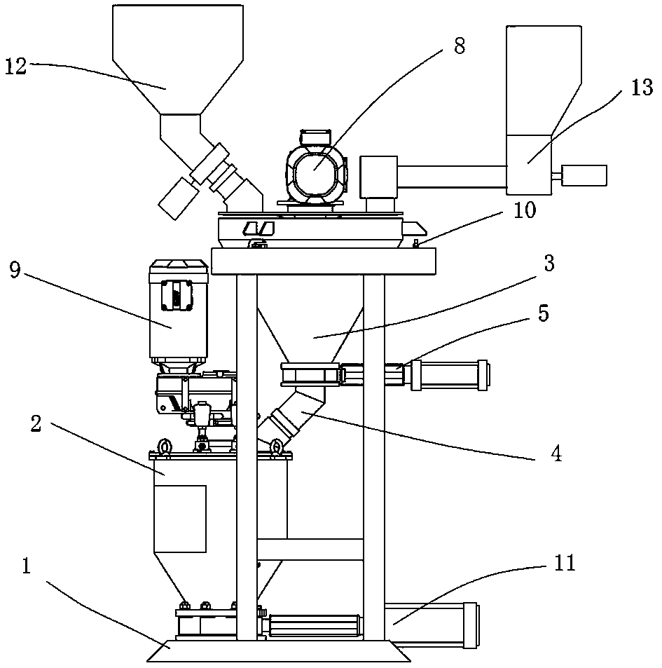
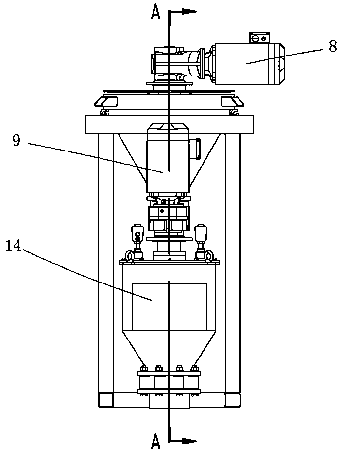
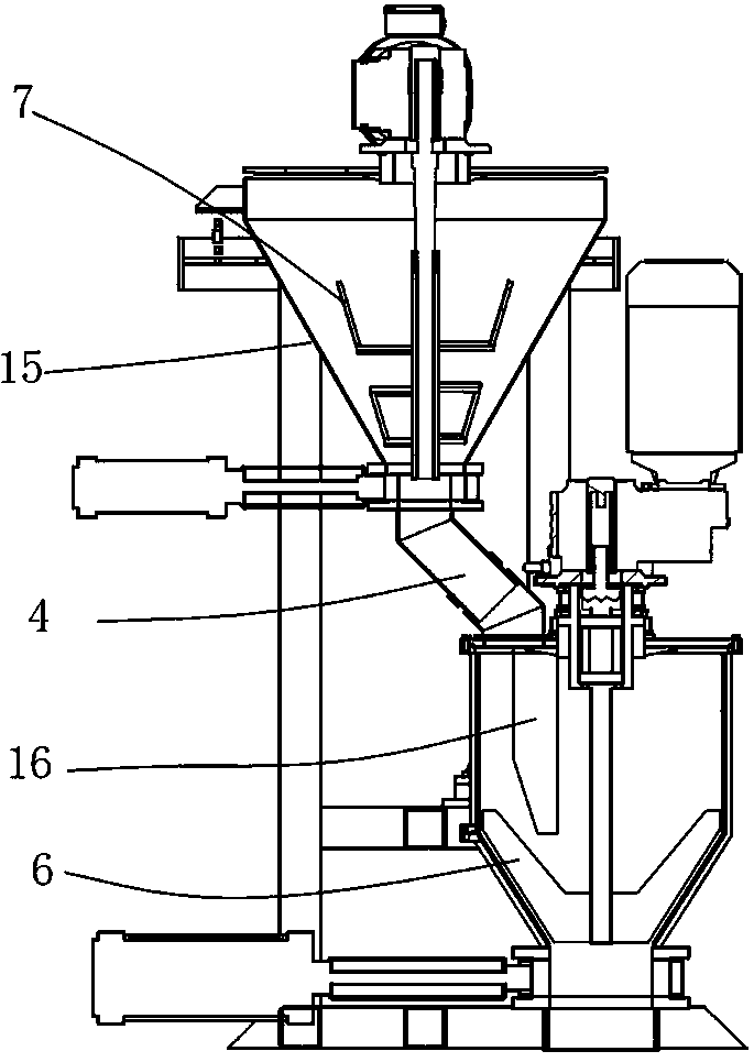
[0042] Embodiment one: see Figure 1 to Figure 3 As shown, an integrated sand mixer includes a frame 1, a final mixing cylinder 2 arranged on the frame, a premixing cylinder 3 arranged above the side of the final mixing cylinder 2, and the outlet at the bottom of the premixing cylinder 3 passes through the The sand pipe 4 is connected to the top feed port of the final mixing cylinder 2, and the sand slide pipe 4 is provided with a knife gate valve 5.

[0043] The premixing barrel 3 is a conical bucket, the upper part of which is connected with a sand bucket 12 and a powder quantitative device 13, and a premixing blade 7 is arranged in the conical bucket, and the premixing blade 7 is driven by a premixing power mechanism 8, and the premixing power mechanism 8 can be composed of a motor and a corresponding deceleration mechanism, and a load cell 10 is arranged on the frame in cooperation with the premixing cylinder 7 . The lower part of the final mixing cylinder 2 is a conical ...


PUM


Abstract

An integrated sand mixer is realized by using a blade stirring sand mixer. The sand mixer has a sand metering device and a mixing drum. The sand metering device is equipped with a pre-mixing blade (7), and is provided with a premixing power mechanism (8) that drives the premixing blades (7), so that the sand quantitative device constitute a pre-mixing cylinder (3); a powder material inlet and a liquid material inlet are respectively arranged on the mixing cylinder, and the outlet of the pre-mixing cylinder (3) is connected to the powder feed port of the mixing drum so that the mixing drum constitute a final mixing drum (2); in the pre-mixing drum (3), quantitative addition of raw sand, quantitative addition of powdered auxiliary materials and premixing of raw sand and powdered auxiliary materials are carried out; the raw sand and liquid resin material pre-mixed with the powdered auxiliary materials enter the final mixing cylinder (2) quantitatively, and the stirring blade (6) is drivento rotate, and the required molding sand is obtained after uniform mixing; and, among them, the final mixing cylinder (2) is performed During the mixing operation, the next cycle of raw sand quantitative addition, powder auxiliary material quantitative addition, and raw sand and powder auxiliary material pre-mixing operations are simultaneously performed in the pre-mixing cylinder (3). An integrated sand mixing method is also disclosed. The sand mixer and sand mixing method realize two-stage sand mixing without increasing the container. The two units can work at the same time. The sand mixingtime is greatly shortened. The relationship between mixing time, sand temperature rise and uniformity can be adjusted arbitrarily.

Description

technical field [0001] The invention relates to a machine used in the metal casting industry, in particular to an integrated sand mixer and a sand mixing method, in particular to an integrated sand mixer and a sand mixing method suitable for use in an inorganic process and a cold core process. Background technique [0002] In the metal foundry industry, the preparation of sand cores is an important part of the foundry process. During this process, it is necessary to uniformly mix sand with binder, curing agent or other additives to prepare molding sand (or called core sand). In the prior art, mixing is usually used to achieve sand mixing. [0003] A conventional sand mixer is usually composed of a sand quantitative unit, a powdery auxiliary material quantitative unit, a liquid material quantitative unit and a sand mixing unit. The sand quantitative unit realizes the raw sand quantitative by volume quantitative method or electronic quantitative method. Electronic quantificat...

Claims


Application Information

Patent Timeline
Patent Type & Authority Applications(China)
IPC IPC(8): B22C5/04
CPCB22C5/0404B22C5/0445B22C5/0472B22C5/044B22C5/0481B01F23/60B01F27/07261B01F27/90B01F33/821
Inventor 徐磊磊陆高春
Owner SUZHOU MINGZHI TECH
Why Eureka
Try Eureka