
Display panel fixture

A display panel and jig technology, applied in the jig field, can solve the problem of display panel being easily bent and deformed, and achieve the effect of reducing panel deformation, avoiding bending, and realizing dimension adjustment.

Active Publication Date: 2022-02-22
SHENZHEN CHINA STAR OPTOELECTRONICS SEMICON DISPLAY TECH CO LTD
View PDF5 Cites 0 Cited by
  • Summary
  • Abstract
  • Description
  • Claims
  • Application Information

AI Technical Summary

Problems solved by technology

[0003] The invention provides a display panel fixture, which is used to solve the technical problem in the prior art that the display panel is easily bent and causes deformation when the dimension is adjusted in a multilayer display device

Method used


Image

  • Display panel fixture
  • Display panel fixture
  • Display panel fixture

Examples


Embodiment

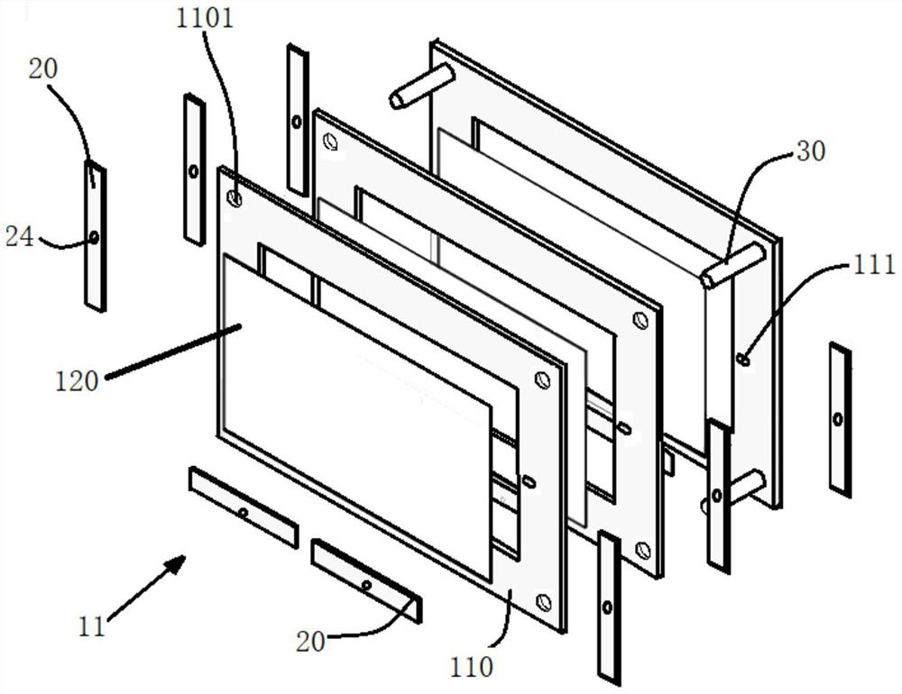
[0041] In this embodiment, the display panel fixture of the present invention includes three rectangular frames 10 , three pressing plates 20 and four adjusting rods 30 .

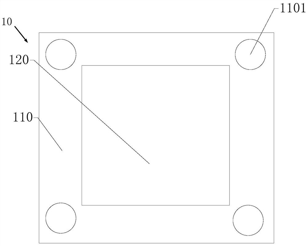
[0042] Such as figure 1 and figure 2 as shown, figure 1 is the exploded view of the display panel fixture in the embodiment, figure 2 is a schematic diagram of the frame in the embodiment. The frame body 10 includes four frames 110 and a working area 120 surrounded by the four frames 110 , wherein the working area 120 is used to see through the display image of the display panel 40 .

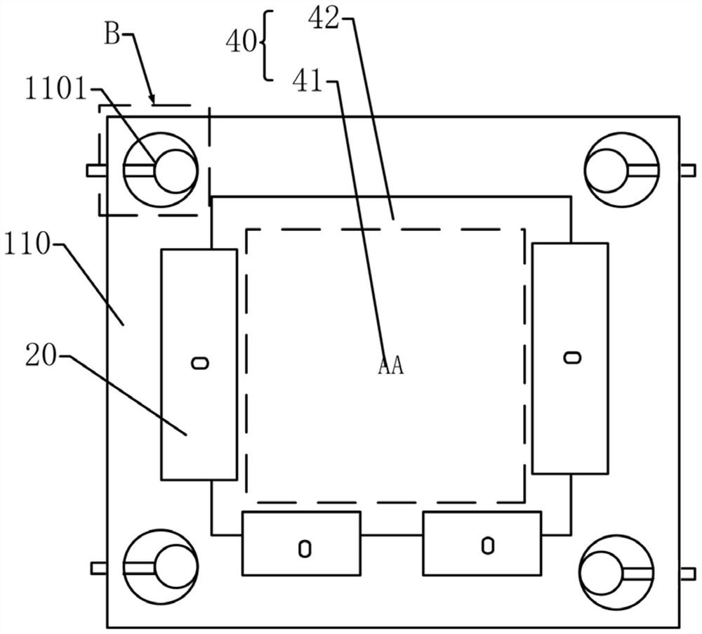
[0043] Such as image 3 and Figure 4 as shown, image 3 It is a partial schematic diagram of the display panel fixture in the embodiment. Figure 4 is a schematic diagram of the in-plane rotation of the display panel in the embodiment. The display panel 40 includes a display area 41 and a non-display area 42. The display area 41 is set corresponding to the work area 120. In particular, the display area 41 of the di...


PUM


Abstract

The invention discloses a display panel jig, which comprises more than two rectangular frame bodies, which are arranged opposite to each other, and each frame body includes four frames; more than two pressing plates, each pressing plate is set opposite to a frame; wherein, at least one The pressing plate includes: a plate body; a first linear protrusion protruding from one side surface of the plate body and arranged at the edge of the plate body; and a second linear protrusion protruding from one side of the plate body surface, and parallel to the first linear protrusion. The beneficial effect of the present invention is that the display panel fixture fixes the display panel through the press plate, and the plate body of the press plate contacts the frame of the display panel, which increases the contact area, effectively reduces the pressure, and avoids deformation of the display panel. The supporting force of the two linear protrusions is offset, which can effectively avoid the bending phenomenon of the display panel due to its own gravity, and improve the service life of the display panel.

Description

technical field [0001] The present application relates to the field of fixtures, in particular to a display panel fixture. Background technique [0002] Today, with the rapid development of display technology, multi-layer display (Multi-layer display, MLD) technology is gradually developed. Multi-layer display is generally used in fields such as HDR display (High-Dynamic Range) and light field three-dimensional display. The method is to stack two or more display panels, and realize HDR display or three-dimensional display through special algorithms. In the three-dimensional display technology of the multi-layer panel method, in order to facilitate the fine-tuning of the display effect when the product leaves the factory (such as strict alignment of pixels, moiré suppression, etc.), and to realize the switching of display parameters (such as display angle of view, display depth of field, etc.) , usually requires a set of adjustable special fixtures. Contents of the inventi...

Claims


Application Information

Patent Timeline
Patent Type & Authority Patents(China)
IPC IPC(8): B25B11/00
CPCB25B11/00
Inventor 霍英东
Owner SHENZHEN CHINA STAR OPTOELECTRONICS SEMICON DISPLAY TECH CO LTD
Learn More