Rotary table for positioning battery compartment top cover and processing device with the same

A technology of processing device and rotary table, applied in positioning device, feeding device, storage device, etc., can solve the problems of inconvenient positioning, affecting punching quality, time-consuming and laborious, etc., to reduce tensile deformation, improve production quality, reduce The effect of production costs

Active Publication Date: 2021-06-18
江西博展自动化科技有限公司
View PDF0 Cites 0 Cited by
  • Summary
  • Abstract
  • Description
  • Claims
  • Application Information

AI Technical Summary

Problems solved by technology

At present, the stamping and punching operations of the top cover will have the following problems: In the stamping process, since there is no auxiliary structure for the reserved concave area, it is very easy to cause the sheet metal to be stretched and deformed when stamping the rib area To adapt to the concave-convex structure, in this way, the sheet metal plate after deformation and thinning will affect the rigidity of the top cover, which in turn will affect the impact resistance, collision resistance and extrusion resistance of the battery compartment
In addition, when the molding position of the reinforcing rib is deep or narrow, the semi-finished top cover is easily stuck on the mold and it is difficult to remove the mold
In the punching process, the top cover after stamping has an uneven structure, which is not convenient for positioning. Therefore, at present, most of the punching operations are performed by manually holding the top cover, which is not only time-consuming and laborious, but also affects the punching process. quality

Method used


Image

  • Rotary table for positioning battery compartment top cover and processing device with the same
  • Rotary table for positioning battery compartment top cover and processing device with the same
  • Rotary table for positioning battery compartment top cover and processing device with the same

Examples


Embodiment 1

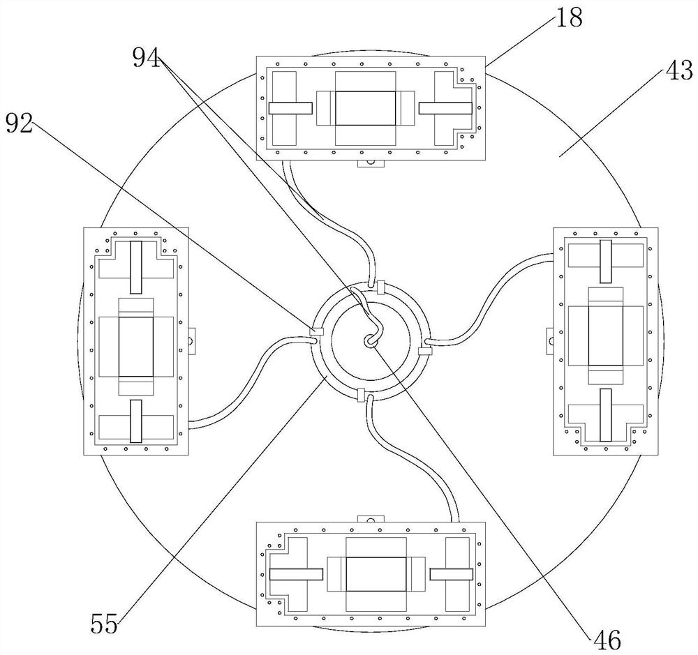
[0091] Such as Figure 2 to Figure 15 As shown, the turntable for positioning the top cover of the battery compartment includes a turntable support base 42 on which a turntable 43 is rotated, and a turntable for driving the turntable 43 to rotate is also arranged on the turntable support base 42 driving device;

[0092] The rotary table support base 42 has a hollow rotary support gas circulation chamber 44, the rotary table support base 42 is provided with a support base air inlet 45 communicating with the rotary support gas circulation cavity 44, and the rotary table support base 42 is connected with a rotary support. The pneumatic universal joint 46 connected to the gas flow chamber 44; the rotary table 43 is provided with several positioning stations arranged in a ring on the rotary table 43, and the lower mold unit driving device is installed on the positioning station. The output end of the mold unit driving device is connected with the lower mold unit;

[0093] The low...

Embodiment 2

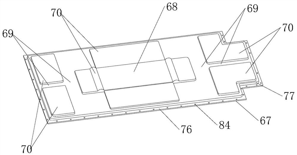
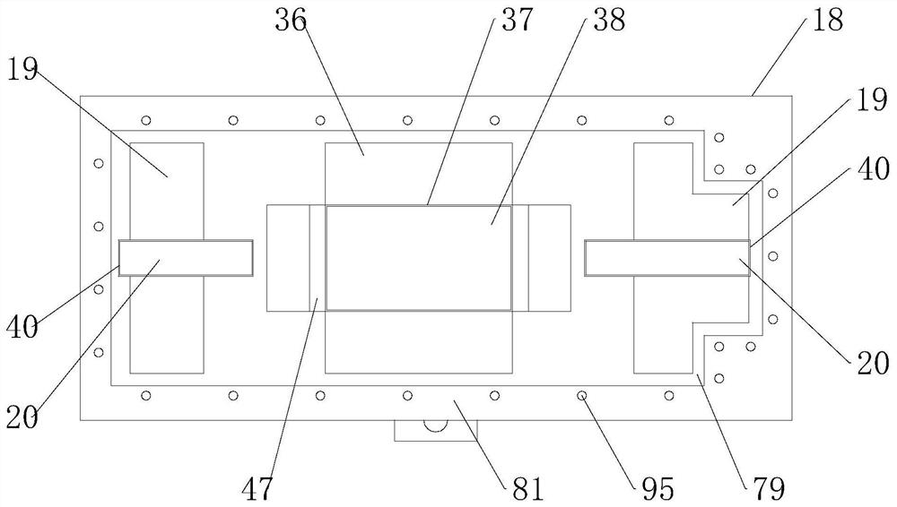
[0102] This embodiment makes the following further limitations on the basis of Embodiment 1: the lower mold middle groove 36 has two left and right symmetrically arranged and spaced middle concave sections 47, and the lower mold support seat 18 is located between the two middle concave sections 47. The area between also offers the gap 37 in the middle part of the lower mold, the gap 37 in the middle part of the lower mold is movably provided with a top piece 38 in the middle part of the lower mold, and the support seat 18 of the lower mold is also provided with a top piece 38 for driving the middle part of the lower mold. The upper part driving device 39 in the middle of the lower mold that moves up and down;

[0103] The lower mold end groove assembly includes at least two lower mold end grooves 19, and the lower mold support seat 18 is also provided with a lower mold end relief gap 40 in the area between two adjacent lower mold end grooves 19. , the gap 40 at the end of the ...

Embodiment 3

[0110] A processing device for the top cover of a battery compartment, comprising an upper mold unit and a rotary table for positioning the top cover of the battery compartment as described in any one of embodiments 1 to 2, the upper mold unit is facing several of the lower mold units Any lower module unit of ;

[0111] The upper mold unit includes an upper mold support seat 1, and the bottom end of the upper mold support seat 1 is provided with an upper mold middle part protrusion 21 matching the lower mold middle part groove 36 in the aforementioned lower mold unit and two located on the upper mold The end protrusion assembly on both sides of the middle protrusion 21, the end protrusion assembly is matched with the lower die end groove assembly in the aforementioned lower die unit;

[0112] The middle protrusion 21 of the upper mold has two middle protrusion segments 22 matching the middle concave segment 47, and the area between the two middle protrusion segments 22 is a re...


PUM


Abstract

The invention discloses a rotary table for positioning a top cover of a battery compartment and a processing device having the rotary table. The rotary table includes a rotary table support seat, a rotary table is rotatably arranged on the rotary table support seat, and a rotary table support seat is further provided with a rotary table for A rotary table drive device for driving the rotary table to rotate; the rotary table support base is connected with a pneumatic universal joint that communicates with the rotary support gas circulation cavity. The lower mold support base has a hollow lower mold support gas circulation cavity, and the top of the lower mold support base is provided with There are a number of lower mold support suction holes communicated with the lower mold support gas flow cavity, the lower mold support seat is also provided with a lower mold support input port communicated with the lower mold support gas flow cavity, and the lower mold support seat is also provided with a lower mold support input port. Punch holes to make way for holes; the rotary table is also provided with a gas annular circulation pipe. The lower die support seat of the present invention can not only provide the lower die unit structure for the punching process, but also provide a stable positioning structure in the punching process, so that the production cost can be reduced and the production quality can be improved.

Description

technical field [0001] The invention belongs to the technical field of new energy vehicle power, and in particular relates to a rotary table for positioning the top cover of a battery compartment and a processing device with the rotary table. Background technique [0002] The battery compartment is mainly responsible for carrying and protecting the battery module, circuit equipment and electronic accessories. It is usually composed of three parts: the upper case assembly, the sealing system and the lower case assembly. In order to meet the requirements of high safety and high reliability, the battery compartment should have strong impact resistance, anti-collision and anti-extrusion performance; at the same time, in order to increase the cruising range, the battery compartment should also meet the requirements of lightweight design. [0003] Although the upper casing assembly is not a load-bearing component, in practical applications, the top cover in the upper casing assemb...

Claims


Application Information

Patent Timeline
Patent Type & Authority Patents(China)
IPC IPC(8): B21D43/14B21D35/00B21D37/10B21D37/12B21D37/14
CPCB21D35/001B21D37/10B21D37/12B21D37/14B21D43/14
Inventor 邹健
Owner 江西博展自动化科技有限公司
Why Eureka
Try Eureka