Combined fan device

A combination and fan technology, applied in the direction of pump devices, circuit devices, battery circuit devices, etc., can solve the problems of single function and poor user experience, and achieve the effect of flexible use

Inactive Publication Date: 2020-07-24
康宝科技股份有限公司
View PDF6 Cites 1 Cited by
  • Summary
  • Abstract
  • Description
  • Claims
  • Application Information

AI Technical Summary

Problems solved by technology

[0003] In order to solve the above problems, the present invention provides a combined fan device. Through technical transformation of the existing fan, it solves the problem that the existing fan needs to be equipped with a fixed bracket before it can be placed on the desktop, has a single function, and has poor user experience.

Method used


Image

  • Combined fan device
  • Combined fan device
  • Combined fan device

Examples


Embodiment Construction

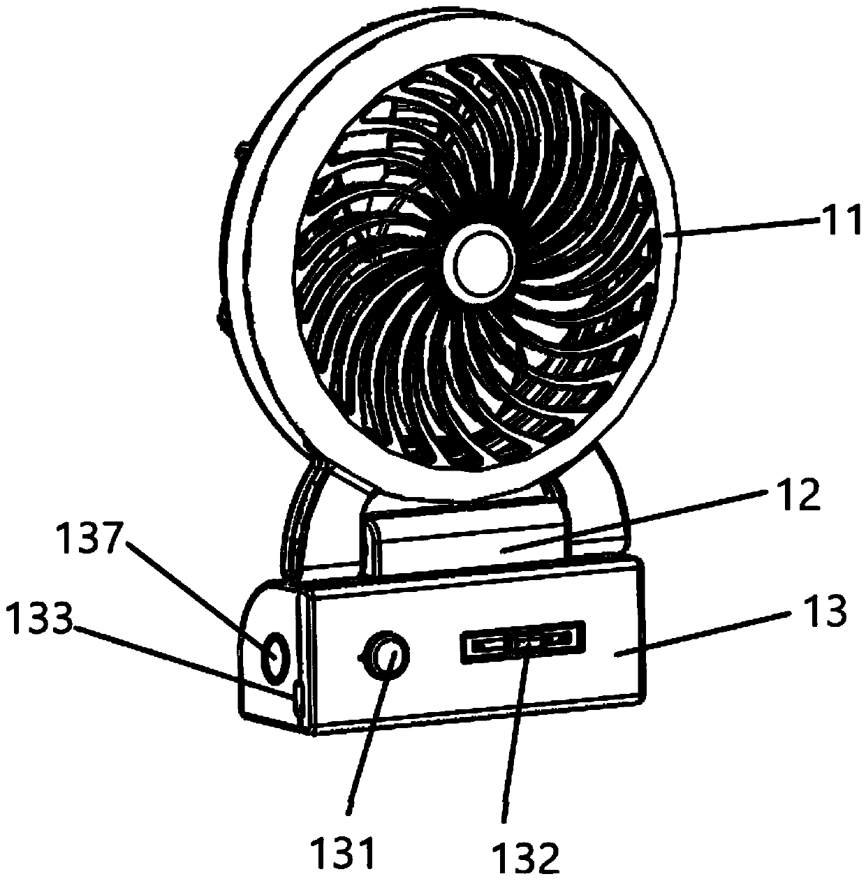
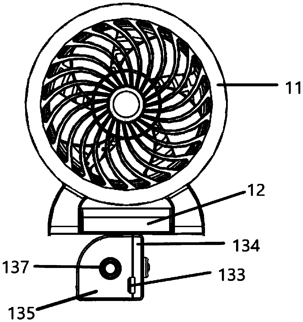
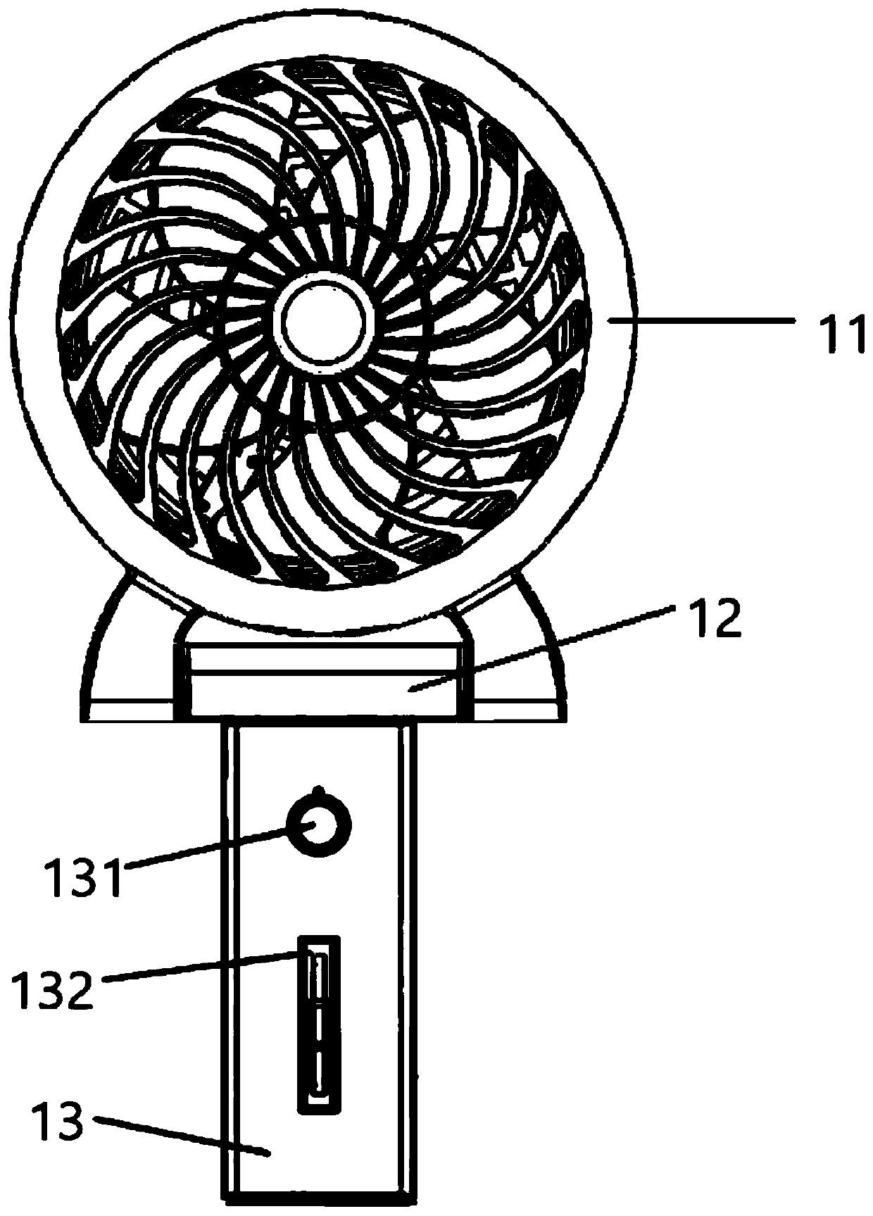
[0032] see Figure 1-4As shown, a combined fan device includes a fan unit. The fan unit includes a fan body 11, a pivot base 12, and a charging base 13. The charging base 13 has a built-in battery and a power control main board connected to the battery; wherein Both sides of the bottom end of the fan body 11 are respectively pivotally connected to both sides of the pivot base 12 through the pivot shaft 111, so that the fan body 11 can pivot 12 relative to the pivot base; wherein the pivot base 12 The bottom end of the charging base 13 is provided with a hollow connecting shaft, and the first connecting terminal assembly electrically connected to the fan body 11 is arranged in the hollow connecting shaft; the upper end surface of the charging base 13 is provided with a first mounting hole 1300, and the charging base 13 A second mounting hole 137 is opened on one side of the first mounting hole 1300 and the second mounting hole 137 is provided with a second connecting terminal a...


PUM


Abstract

The invention provides a combined fan device. A fan body can rotate around a pivot joint base at any angle within the range of 180 degrees, so that the angle of the fan body is adjusted, and thereforethe needed angle is conveniently selected for achieving air blowing. Air is blown to any target without dead angles, and therefore the fan device can achieve the effect of a household fan. Due to thefact that a charging base can rotate, no supporting accessory needs to be additionally added in the process of rotating the charging base left and right by 90 degrees, and use is more flexible. The pivot joint base and the charging base are detachable, the detached charging base can serve as a power bank, a second mounting hole formed in one side of the charging base and a connecting shaft of thepivot joint base are assembled, and the fan can become a handheld fan from a seated fan. The charging base and an automatic rotary base or clip accessory can be assembled, the charging base, the pivot joint base and the automatic rotary base are combined, and the fan can be fixed at any position. Thus, the situation that the arm of a user is painful and the fan can only be put on a tabletop is greatly reduced.

Description

technical field [0001] The invention relates to the field of fans, in particular to a combined fan device. Background technique [0002] In the prior art, the function of the household fan can only be obtained by connecting it to an alternating current, and its portability and practicability are limited. Therefore, a portable fan is introduced in the prior art, but the portable fan in the prior art has the following disadvantages: when the wind power of the portable fan increases, it is easy to fall down, and it needs to be equipped with a fixed bracket to be placed on the desktop for use; the portable fan in the prior art Only the most basic air supply function, its function is single, and the user experience is not good. After solving the problems of wind force and noise, the present invention can replace household fans and achieve a breakthrough in the field of use of portable fans in addition to the patent features of the application. Contents of the invention [000...

Claims


Application Information

Patent Timeline
Patent Type & Authority Applications(China)
IPC IPC(8): F04D25/08F04D29/00F04D29/64F16M13/02H02J7/00
CPCF04D25/0673F04D25/08F04D25/084F04D29/002F04D29/646F16M13/02H02J7/0042
Inventor 李咏康
Owner 康宝科技股份有限公司
Why Eureka
Try Eureka