Machining method of aspherical cylindrical mirror

A processing method and cylindrical mirror technology, applied in the direction of stone processing tools, stone processing equipment, work accessories, etc., can solve the problems of insufficient precision, low processing precision, limited processing range, etc., to ensure high precision and accurate distance. Effect

Active Publication Date: 2020-07-28
BEIJING INSTITUTE OF TECHNOLOGYGY
View PDF7 Cites 1 Cited by
  • Summary
  • Abstract
  • Description
  • Claims
  • Application Information

AI Technical Summary

Problems solved by technology

[0003] Although slow tool servo turning can complete the processing of aspheric cylindrical mirrors with high precision, it cannot process aspheric cylindrical mirrors with large depth-to-diameter ratio due to the influence of the tool back angle; slow tool servo milling is not affected by the tool back angle. Due to the influence of large depth-to-diameter ratio, the processing of aspheric cylindrical mirrors with large depth-to-diameter ratio can be realized, but due to the influence of uneven distribution of C-axis track points, the processing accuracy is low; ultra-precision planing can realize high-precision, large depth-to-diameter ratio aspheric surface Processing of cylindrical mirrors, but requires three high-precision linear axes, X-axis, Y-axis and Z-axis
The integration of three high-precision linear axes on the machine tool greatly increases the manufacturing cost of the machine tool. At the same time, when the depth of the aspheric cylindrical mirror is greater than the range of the Y-axis, the ultra-precision planing process cannot complete high-precision, Processing of aspheric cylindrical mirror with large depth-to-diameter ratio (depth greater than Y-axis range)
[0004] In summary, the above three processing methods have the problems of limited processing range, insufficient precision, or high cost. Therefore, we need a processing method that can achieve low cost, high precision, and large depth-to-diameter ratio aspheric cylindrical mirrors.

Method used


Image

  • Machining method of aspherical cylindrical mirror
  • Machining method of aspherical cylindrical mirror
  • Machining method of aspherical cylindrical mirror

Examples


Embodiment 1

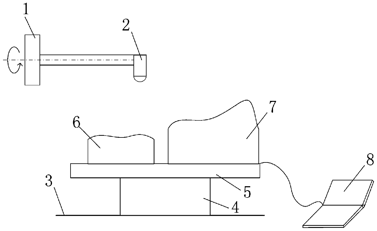
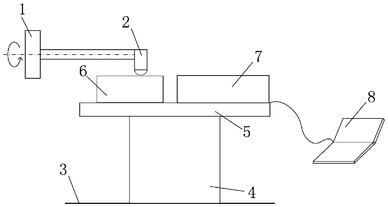
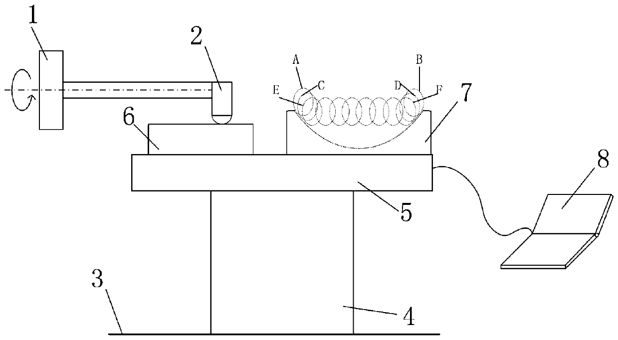
[0033] like Figure 1-Figure 5 As shown, the present embodiment provides a processing method of an aspheric cylindrical mirror, and the equipment used is a two-axis ultra-precision machine tool. The two-axis ultra-precision machine tool has two ultra-precision linear axes X-axis and Z-axis. Cutter 2 is installed on the machine tool spindle 1 of lathe, and the preferred cutter head of cutter 2 is the diamond cutter of circular arc in the present embodiment; Specifically comprises the following steps:

[0034] Step S01, such as figure 1 As shown, a rough adjustment displacement platform 4 and a fine adjustment displacement platform 5 are placed on the machine tool table 3, and the fine adjustment displacement platform 5 is placed on the coarse adjustment displacement platform 4. By making the lower surface of the coarse adjustment displacement platform 4 close to the upper surface of the machine tool table 3, and the lower surface of the fine adjustment displacement platform 5 ...

Embodiment 2

[0041] like Image 6 As shown, on the basis of the first embodiment, step S06 is further included, and step S01 to step S05 are repeated in the Z direction, so as to obtain the processing of the aspheric cylindrical mirror array.

[0042] Through the above method, not only the processing of the aspheric cylindrical mirror array with large depth-to-diameter ratio and processing depth greater than the Y-axis range is realized, but also the consistency of the array is high, so that a high-precision aspheric cylindrical mirror array can be obtained.


PUM


Abstract

The invention discloses a machining method of an aspherical cylindrical mirror. The machining method of the aspherical cylindrical mirror comprises the steps that the feed in the direction of a Y axisis realized by installing a coarse adjusting displacement platform and a fine adjusting displacement platform from bottom to top on a machine tool table; first, machining is carried out by adjustingthe fine adjusting displacement platform, when the range M of the fine adjusting displacement platform is reached, the fine adjusting displacement platform is lowered and the coarse adjusting displacement platform is raised, after precision correction, a tool tip is coincident with a datum of a measurement block, the high-precision feed in the direction of the Y axis is realized by constantly adjusting the fine adjusting displacement platform, and the machining of the aspheric surface cylindrical mirror is completed by repeating the steps. By combining the fine adjusting displacement platformwith the coarse adjusting displacement platform, the form of high-precision feed in the direction of the Y axis is realized, and the machining of the aspherical cylindrical mirror with low cost, highprecision and large depth ratio is realized on a two-axis ultra-precision machine tool.

Description

technical field [0001] The invention relates to the field of precision optical element processing, in particular to a processing method for an aspheric cylindrical mirror. Background technique [0002] At present, there are three processing methods for aspheric cylindrical mirrors: slow tool servo turning, slow tool servo milling and ultra-precision planing. Slow tool servo turning is a processing method in which the single crystal diamond turning tool carves an aspheric cylindrical mirror on the surface of the workpiece through the linkage of the two linear axes of the X axis and the Z axis and the rotary axis C axis; the slow tool servo milling is carried out on the machine tool. Add high-speed milling axis accessories, and then install the diamond milling cutter on the milling axis, through the linkage of the linear axis X-axis, Z-axis and the rotary axis C-axis, so that the high-speed rotating diamond milling cutter can fit and process an aspheric cylinder on the surface...

Claims


Application Information

Patent Timeline
Patent Type & Authority Applications(China)
IPC IPC(8): B28D1/00B28D7/00
CPCB28D1/00B28D7/00B28D7/005
Inventor 周天丰阮本帅周佳王子凡刘朋梁志强王西彬
Owner BEIJING INSTITUTE OF TECHNOLOGYGY
Why Eureka
Try Eureka