
Auxiliary tilting device of rearview mirror

A technology of tilting device and reflector, which is applied in the field of reflector, can solve the problems of troublesome adjustment, limited visual range, and inability to see rear tires, etc., and achieves the effect of convenient adjustment

Inactive Publication Date: 2020-07-28
SUZHOU RUIDAJU AUTOMATIC EQUIP CO LTD
View PDF0 Cites 0 Cited by
  • Summary
  • Abstract
  • Description
  • Claims
  • Application Information

AI Technical Summary

Problems solved by technology

Existing car rearview mirrors are equipped with driving motors, which can be triggered to adjust the angles of the rearview mirrors through the adjustment buttons in the car. However, the visual range of existing rearview mirrors is limited, but you can see When viewing the far side area, the position near the rear tires of the vehicle cannot be seen, and when the position of the rear tires of the vehicle can be seen, the rear side distant view is lost;
[0003] Under normal circumstances, the rearview mirror is generally adjusted so that you can see the distant area on the rear side, so that you can observe the vehicles coming from behind when changing lanes or turning; The reflector needs to be adjusted so that the wheels and the rear of the car can be seen, and it needs to be adjusted back to the original driving position after reversing the car. However, the existing adjustment device needs to be adjusted repeatedly in multiple steps, and the adjustment is more troublesome

Method used


Image

  • Auxiliary tilting device of rearview mirror
  • Auxiliary tilting device of rearview mirror
  • Auxiliary tilting device of rearview mirror

Examples


Embodiment Construction

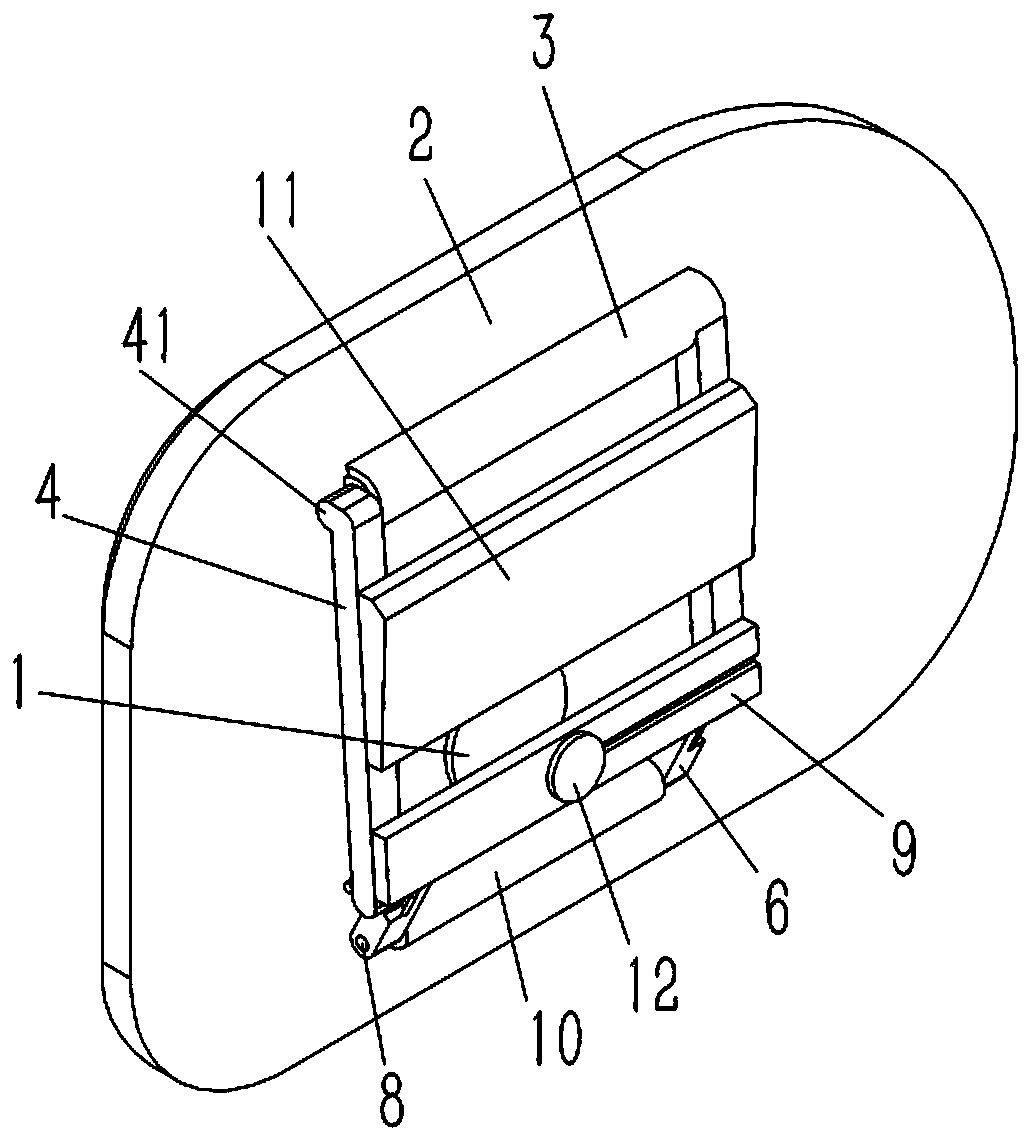
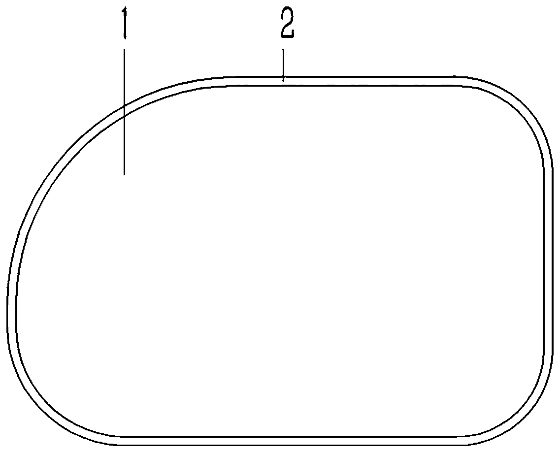
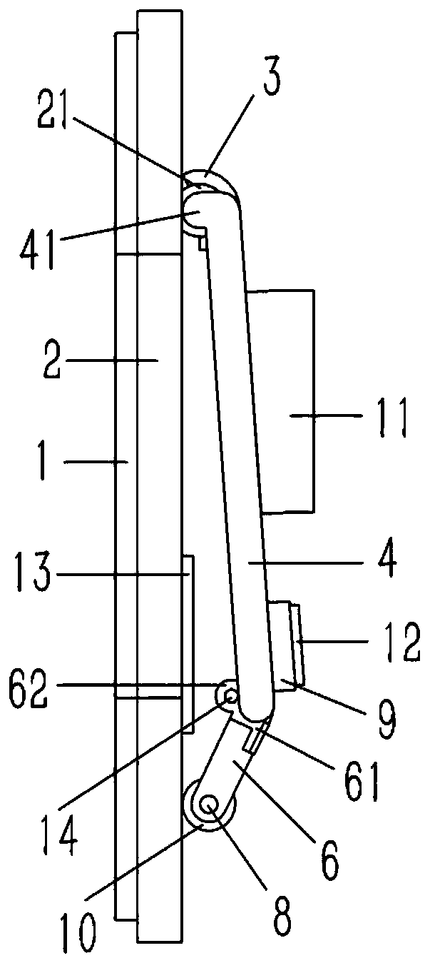
[0020] Example: see Figure 1 to 4 As shown, an auxiliary tilting device for a rear-view mirror includes a mirror 1, which is inserted and fixed in a mirror holder 2. The upper end of the back of the mirror holder 2 is formed with a D-shaped clip 21 on the clip 21 The insert sleeve is provided with an arc-shaped ferrule 3, the two ends of the ferrule 3 are fixedly connected with an oblique first connecting rod 4, and a first connecting shaft 5 is inserted and fixed between the lower ends of the first connecting rod 4. The two ends of the connecting shaft 5 are sleeved with a torsion spring 7 and an inclined second connecting rod 6, one end of the torsion spring 7 is inserted into the first connecting rod 4, and the other end is inserted into the second connecting rod 6. The lower end of the second connecting rod 6 abuts against the back of the mirror holder 2; the upper and lower ends of the rear end of the first connecting rod 4 are respectively fixed with an upper connecting ...


PUM


Abstract

The invention discloses an auxiliary tilting device of a rearview mirror. The device comprises a reflective mirror, the reflective mirror is inserted and fixed in a mirror support; a D-shaped clampingstrip is formed at the upper end of the back surface of the mirror support; an arc-shaped clamping sleeve is inserted into the clamping strip in a sleeving manner; inclined first connecting rods arefixedly connected to the two ends of the clamping sleeve, a first connecting shaft is inserted and fixed between the lower ends of the first connecting rods, torsional springs and inclined second connecting rods are inserted into the two ends of the first connecting shaft, one ends of the torsional springs are inserted into the first connecting rods, the other ends of the torsional springs are inserted into the second connecting rods, and the lower ends of the second connecting rods abut against the back face of the mirror support; an upper connecting plate and a lower connecting plate are fixed to the upper end and the lower end of the rear end face of the first connecting rods respectively, an electromagnet is inserted and fixed to the lower connecting plate, and an iron sheet opposite to the electromagnet is bonded and fixed to the back face of the mirror support.

Description

Technical field [0001] The present invention relates to the technical field of mirrors, and more specifically to an auxiliary tilting device for rear-view mirrors. Background technique [0002] The rearview mirror of the car is located on the left and right sides of the head of the car. It mainly uses the principle of the mirror to reflect the situation behind, side and below the car, so that the driver can indirectly see the situation of these positions. It plays a " The role of the "second eye" expands the driver's field of vision. Existing car rearview mirrors are equipped with a driving motor. The driving motor can be triggered to adjust the angles of the rearview mirror through the adjustment button in the car. However, the visual range of the rearview mirror of the existing vehicle is limited, but the rearview mirror can be seen. When you are in the far side area, you cannot see the position near the rear tires of your car, and when you can see the position of the rear tir...

Claims


Application Information

Patent Timeline
Patent Type & Authority Applications(China)
IPC IPC(8): B60R1/072
CPCB60R1/072
Inventor 胡虎
Owner SUZHOU RUIDAJU AUTOMATIC EQUIP CO LTD
Learn More