Door with buffer effect

A door body and shaft technology, applied in the field of doors with a buffer effect, can solve the problems of wear or tear of rubber strips, inability to achieve buffer silence, damage to the door body structure, etc.

Active Publication Date: 2020-07-28
抚州市中小企业服务有限公司
View PDF6 Cites 1 Cited by
  • Summary
  • Abstract
  • Description
  • Claims
  • Application Information

AI Technical Summary

Problems solved by technology

[0003] The common cushioning silent door is mostly to add a rubber strip around the door or the door frame. When the door is closed, the rubber strip can buffer the collision between the door body and the door frame, so as to achieve the effect of noise reduction. However, after a long time of use, the rubber strip will inevitably Wear or tear will occur, and at this time, the purpose of cushioning and silence cannot be achieved. In addition, in order to prevent the rubber strip from falling off during processing, it is often embedded in the door frame or door body. Therefore, replacing the rubber strip also has certain advantages. Difficulty, even the structure of the door body will be damaged when it is replaced. Therefore, we propose a door with a cushioning effect

Method used


Image

  • Door with buffer effect
  • Door with buffer effect
  • Door with buffer effect

Examples


Embodiment 1

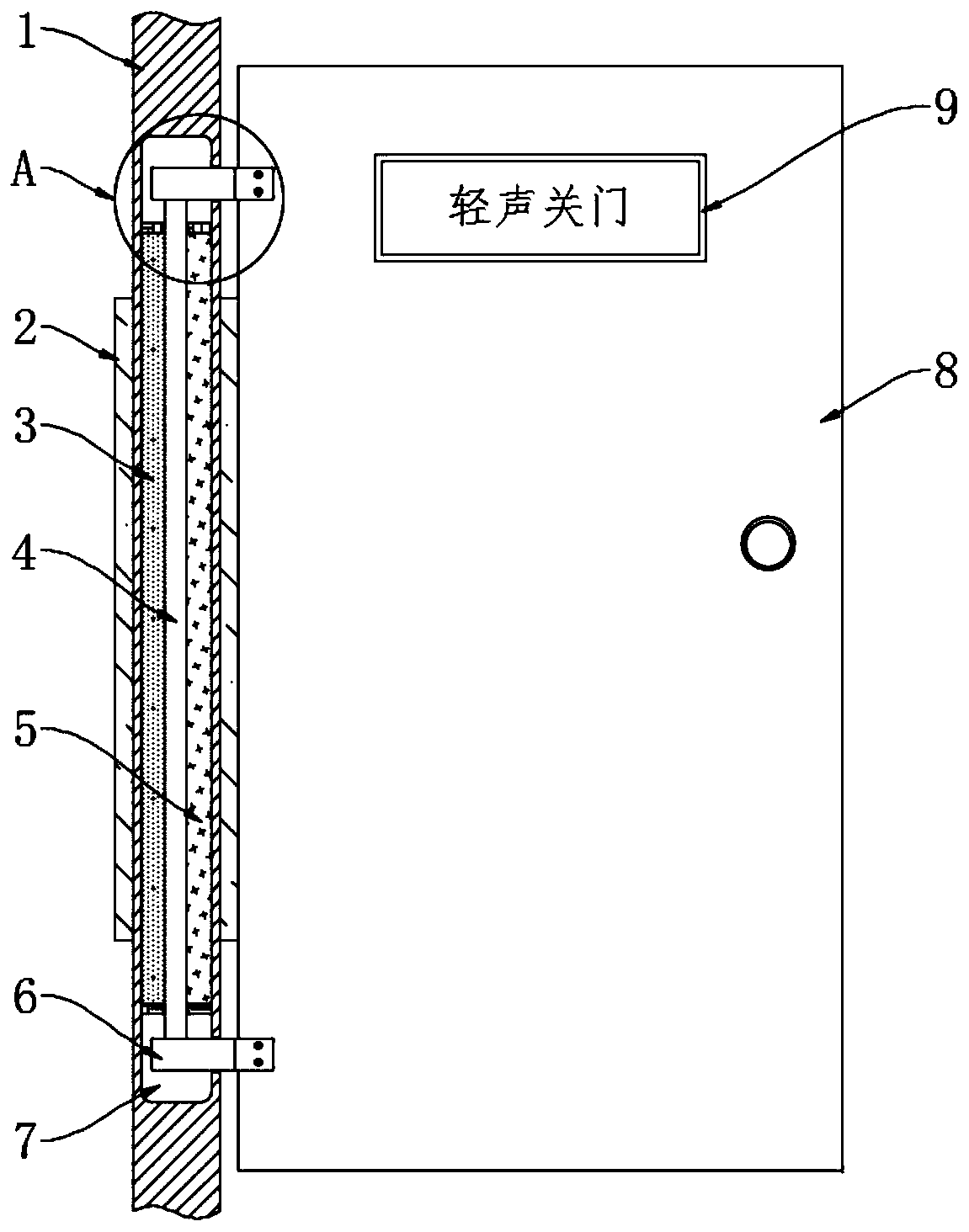
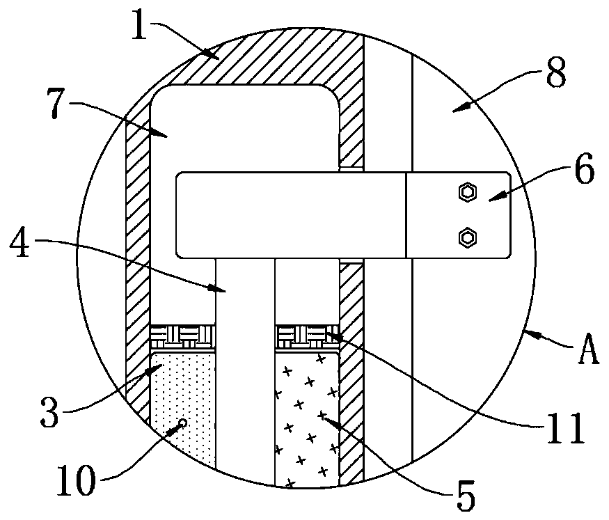
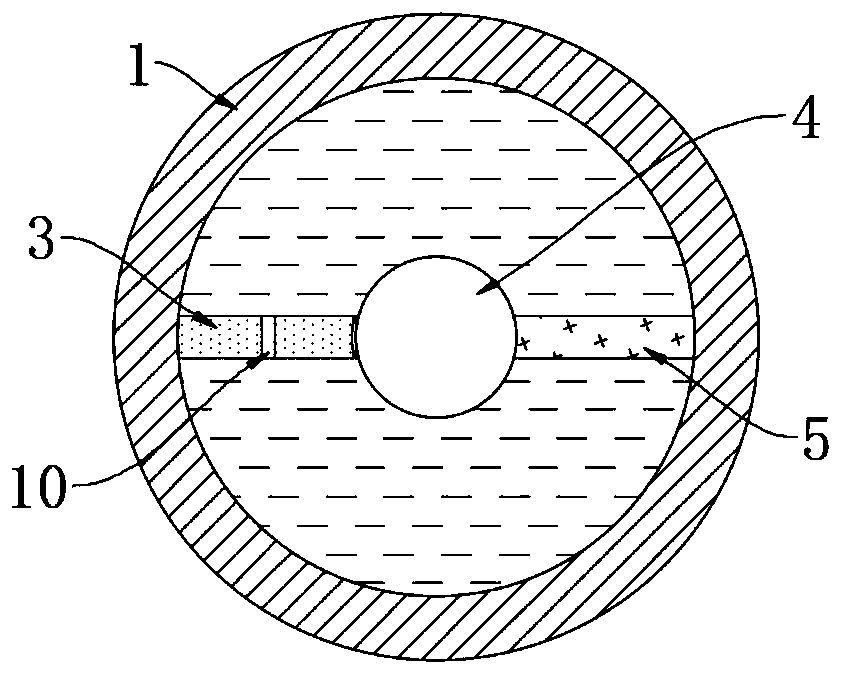
[0028] refer to Figure 1-3 , a door with a buffer effect, including a rotating shaft 1 and a door body 8, the door body 8 is rotationally connected with the rotating shaft 1 through a shaft sleeve 2, and the shaft sleeve not only plays the role of connecting the door body 8 and the rotating shaft 1, but also supports the door The role of the body 1, the rotating shaft 1 is provided with a hollow cavity 7, the upper and lower ends of the hollow cavity 7 are symmetrically sealed with a sealing ring 11, the center of the two sealing rings 11 is installed with a rotating rod 4, and the rotating rod 4 and The two sealing rings 11 are sealed and slidingly connected, two semi-arc grooves are symmetrically opened on the rotating shaft 1, and connecting rods 6 are fixedly connected to both ends of the rotating rod 4, and each connecting rod 6 is far away from the rotating rod 4 One end of each is fixedly connected with the door body 8 through a semi-arc groove;

[0029] A fixed plate...

Embodiment 2

[0035] refer to Figure 4-6 , the present embodiment differs from Embodiment 1 in that: the identification plate 9 includes a housing, a see-through window 901 and a plate 902, a transparent capsule 15 is thermally fused in the housing, and the transparent capsule 15 is located between the plate 902 and the housing Between the inner side walls, the transparent capsule 15 can be regarded as the background of the plate 902 , and the color change of the transparent capsule 15 can be seen through the plate 902 .

[0036] In this embodiment, the rotating rod 4 and the connecting rod 6 are provided with a thin tube 14, the thin tube 14 includes a horizontal end and a vertical end, the horizontal end of the thin tube 14 communicates with the transparent capsule 15, and the thin tube 14 vertical end The end nozzle runs through the side wall of the rotary rod 4 and extends to the outside of the rotary rod 4, and a pressure valve 13 is installed at the vertical end of the thin tube 14. ...


PUM


Abstract

The invention discloses a door with a buffer effect. The door comprises a rotating shaft and a door body, the door body is rotatably connected with the rotating shaft through a shaft sleeve, a hollowcavity is formed in the rotating shaft, seal rings are symmetrically mounted on the upper end and the lower end of the hollow cavity in a seal manner, a rotating rod is jointly mounted on the centersof the two seal rings in a penetrating manner, the rotating rod is in seal sliding connection with the two seal rings, two semi-arc grooves are formed in the rotating shaft symmetrically, connecting rods are fixedly connected to the two ends of the rotating rod, the ends, away from the rotating rod, of each connecting rod is fixedly connected with the door body through the corresponding semi-arc groove, the service life is long, flowing speed of hydraulic oil in the door is limited by a flow limiting hole, when the door body bears strong thrust, the hydraulic oil cannot rapidly flow, the aim of reducing the rotating speed of the rotating rod and the door body can be achieved, the acute collision of the door body and a door frame can be avoided, the effect of protecting the door body and the door frame can be achieved, and generation of the noise is reduced.

Description

technical field [0001] The invention relates to the technical field of doors, in particular to a door with a buffer effect. Background technique [0002] With the development of the society and the progress of the economy, the types of doors are becoming more and more abundant. People will choose doors with different functions according to the usage scenarios. Generally, automatic glass doors are installed; in study and office areas, buffer and silent doors are mostly installed. [0003] The common cushioning mute door is mostly to add a rubber strip around the door or the door frame. When the door is closed, the rubber strip can buffer the collision between the door body and the door frame, so as to achieve the effect of noise reduction. However, after a long time of use, the rubber strip will inevitably Wear or tear will occur, and at this time, the purpose of cushioning and silence cannot be achieved. In addition, in order to prevent the rubber strip from falling off dur...

Claims


Application Information

Patent Timeline
Patent Type & Authority Applications(China)
IPC IPC(8): E06B3/36E05F3/14E06B7/28G09F7/00
CPCE05F3/14E06B3/36E06B7/28G09F7/00
Inventor 房莉莉鄂军伟冷辉
Owner 抚州市中小企业服务有限公司
Why Eureka
Try Eureka