
A method for unifying poses and postures of equipment groups in fully mechanized mining face

A technology of a fully mechanized mining face and a unified method, which is applied to the field of equipment group pose control in a fully mechanized mining face, can solve problems such as affecting production efficiency, real-time equipment movement, accuracy, unguaranteed coordination and unity, and misoperation.

Active Publication Date: 2021-11-05
CCTEG COAL MINING RES INST
View PDF6 Cites 0 Cited by
  • Summary
  • Abstract
  • Description
  • Claims
  • Application Information

AI Technical Summary

Problems solved by technology

At present, each equipment and its control system operate independently, and the coordinated linkage control is limited to the application of simple functions such as sequential start and stop, and group shifting; while automatic follow-up shifting, coal flow balance control, etc. require equipment position accuracy Higher functions, due to the inaccurate measurement of the spatial pose information (including position and attitude information) of the equipment group in the fully mechanized mining face, it is impossible to achieve continuous automatic operation control in most cases
[0003] At present, a large number of frequent and dynamic linkage control between various equipment can only be completed manually, and the real-time performance, accuracy, and coordination of equipment movement cannot be guaranteed, which not only affects production efficiency, but also easily occurs Misoperation leads to equipment damage and safety production accidents
The root cause is that the pose measurement data between the equipment is local and isolated, and it is still impossible to obtain unified pose information of the equipment group (mainly in the form of coordinates), so that the equipment group of the fully mechanized mining face cannot Motion control in a unified coordinate system

Method used


Image

  • A method for unifying poses and postures of equipment groups in fully mechanized mining face
  • A method for unifying poses and postures of equipment groups in fully mechanized mining face
  • A method for unifying poses and postures of equipment groups in fully mechanized mining face

Examples


Embodiment Construction

[0029] Embodiments of the present invention will be described in detail below in conjunction with the accompanying drawings.

[0030] It should be clear that the described embodiments are only some of the embodiments of the present invention, rather than all of them. In order to illustrate the present invention more clearly, many technical details are described in the following specific embodiments. Those skilled in the art should understand that, The invention may be practiced without some of these details. In addition, in order to highlight the gist of the present invention, some methods, means, components and their applications that are well known to those skilled in the art are not described in detail, but this does not affect the implementation of the present invention. Based on the embodiments of the present invention, all other embodiments obtained by persons of ordinary skill in the art without creative efforts fall within the protection scope of the present invention....


PUM


Abstract

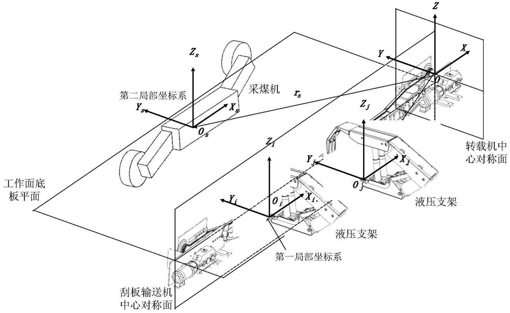
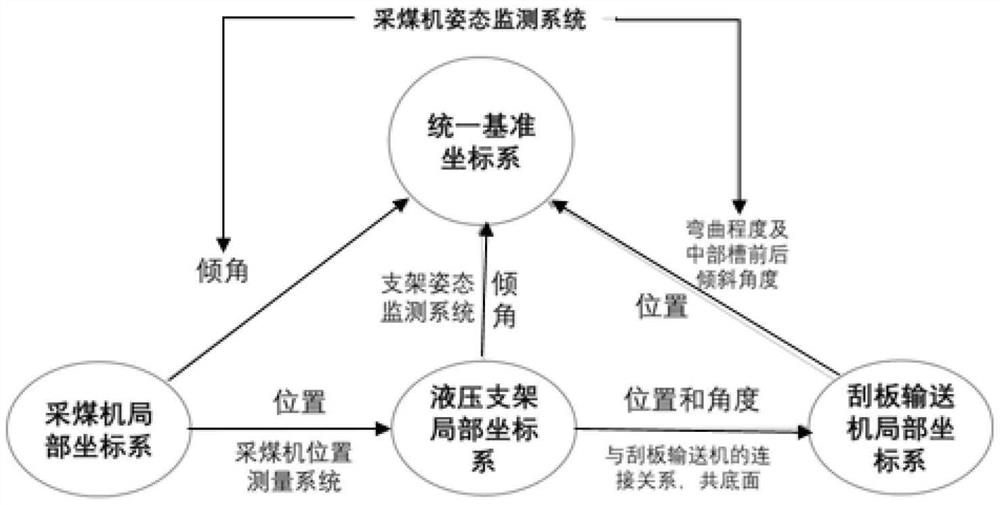
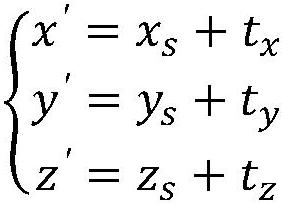
The invention discloses a method for unifying poses and postures of equipment groups in fully mechanized mining faces, which relates to the technical field of equipment monitoring and control in coal mine fully mechanized mining faces. Motion control in a unified coordinate system. Including: building a unified reference coordinate system; consolidating the first local coordinate system on all hydraulic supports in the working face; consolidating the second local coordinate system on the coal mining machine body; Consolidate the third local coordinate system; transform the second local coordinate system to the first local coordinate system based on the positional relationship between the shearer and the hydraulic support; transform the first local coordinate system to the second local coordinate system based on the connection relationship between the hydraulic support and the middle tank Three local coordinate systems; transforming the third local coordinate system into a unified reference coordinate system based on the size parameters of the scraper conveyor itself. The invention is suitable for monitoring and controlling the equipment group of fully mechanized mining face.

Description

technical field [0001] The invention relates to the technical field of equipment monitoring and control in a coal mine fully mechanized mining face, in particular to a method for unifying poses and postures of a fully mechanized mining face equipment group. Background technique [0002] Underground fully mechanized mining face equipment mainly includes hydraulic supports, shearers and scraper conveyors. At present, each equipment and its control system operate independently, and the coordinated linkage control is limited to the application of simple functions such as sequential start and stop, and group shifting; while automatic follow-up shifting, coal flow balance control, etc. require equipment position accuracy Higher functions, due to the inaccurate measurement of the spatial pose information (including position and attitude information) of the equipment group in the fully mechanized mining face, the continuous automatic operation control cannot be realized in most case...

Claims


Application Information

Patent Timeline
Patent Type & Authority Patents(China)
IPC IPC(8): E21F17/18E21F17/00E21F13/06E21D15/44E21C35/24E21C35/00
CPCE21C35/00E21C35/24E21D15/44E21F13/066E21F17/00E21F17/18
Inventor 任怀伟赵国瑞马英李帅帅杜毅博周杰巩师鑫庞义辉文治国杜明
Owner CCTEG COAL MINING RES INST
Learn More