A half clasp fatigue test assembly and fatigue test device
A technology of fatigue testing and half snap ring, which is applied in the direction of measuring devices, testing of mechanical components, testing of machine/structural components, etc., can solve the problems of long test period and high manufacturing cost, and achieve shortened test period and reduced manufacturing cost , improve the effect of the solution cycle
- Summary
- Abstract
- Description
- Claims
- Application Information
AI Technical Summary
Problems solved by technology
Method used
Image

Examples
Embodiment Construction
[0028] In order to make the purpose, technical solution and advantages of the present invention more clear, the embodiments of the present invention will be described in detail below in conjunction with the accompanying drawings. It should be noted that, in the case of no conflict, the embodiments in the present application and the features in the embodiments can be combined arbitrarily with each other.
[0029] The following specific embodiments provided by the present invention can be combined with each other, and the same or similar concepts or processes may not be repeated in some embodiments.
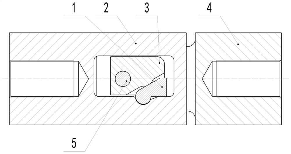
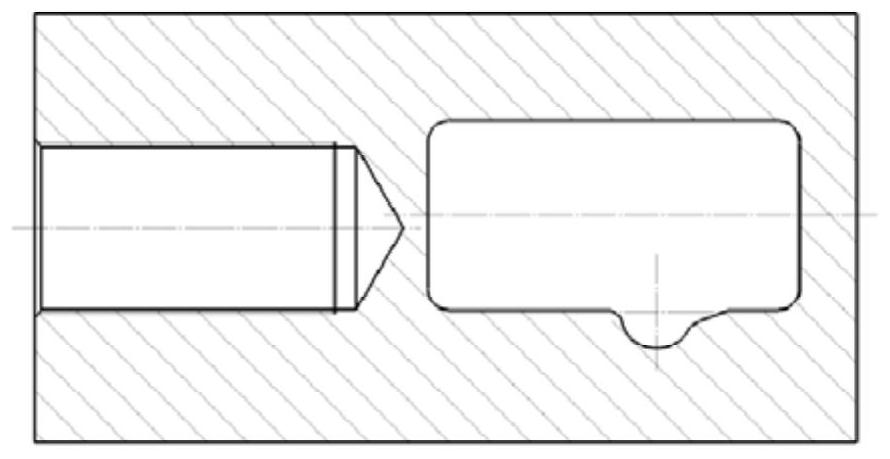
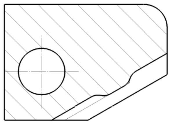
[0030] figure 1 It is a schematic structural diagram of a half clasp fatigue test assembly provided by an embodiment of the present invention. The half snap ring fatigue test assembly provided in this embodiment may include: a fixed seat 2, a pull block 3, a pull plate 4, a positioning pin 5 and a half snap ring sample 1, wherein the half snap ring sample 1 is a half snap ring Ra...
PUM
 Abstract
Description
Claims
Application Information