Locking structure for low-voltage switch cabinet

A low-voltage switchgear and cabinet technology, applied in the field of low-voltage switchgear, can solve the problems of inability to carry out lubricating oil, smear work, and inability to disassemble related parts.

Inactive Publication Date: 2020-07-31
江苏海潮电气科技有限公司
View PDF0 Cites 1 Cited by
  • Summary
  • Abstract
  • Description
  • Claims
  • Application Information

AI Technical Summary

Problems solved by technology

[0004] In view of the above situation, in order to overcome the defects of the prior art, the present invention provides a locking structure for low-voltage switchgear, which effectively solves the problem of partial damage of the locking structure for low-voltage switchgear on the market due to related problems. Components cannot be disassembled, resulting in the failure of the locking mechanism to work normally, and the problem that lubricating oil cannot be applied when the low-voltage switchgear is in a closed state

Method used


Image

  • Locking structure for low-voltage switch cabinet
  • Locking structure for low-voltage switch cabinet
  • Locking structure for low-voltage switch cabinet

Examples


Embodiment 1

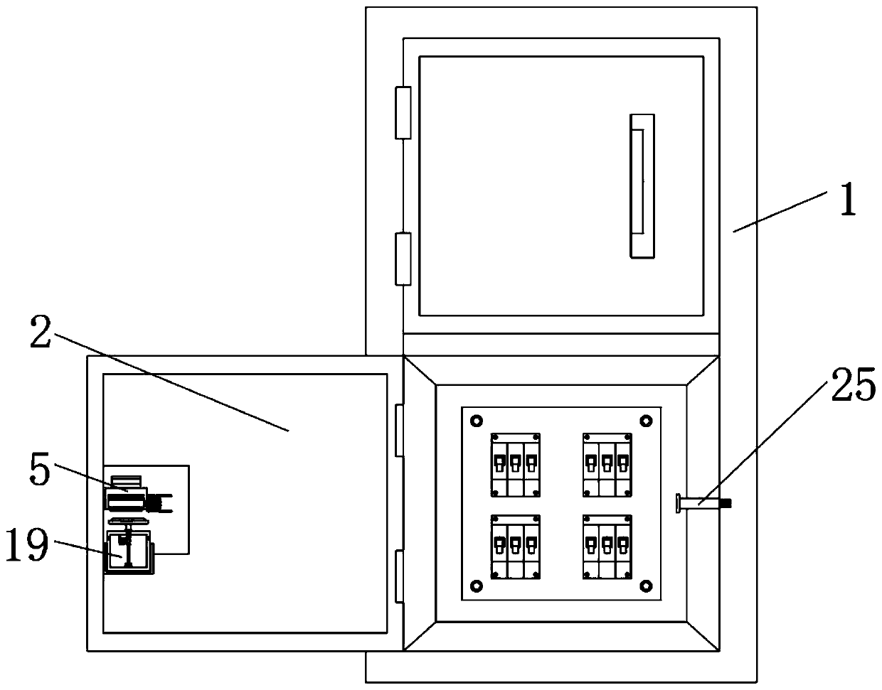
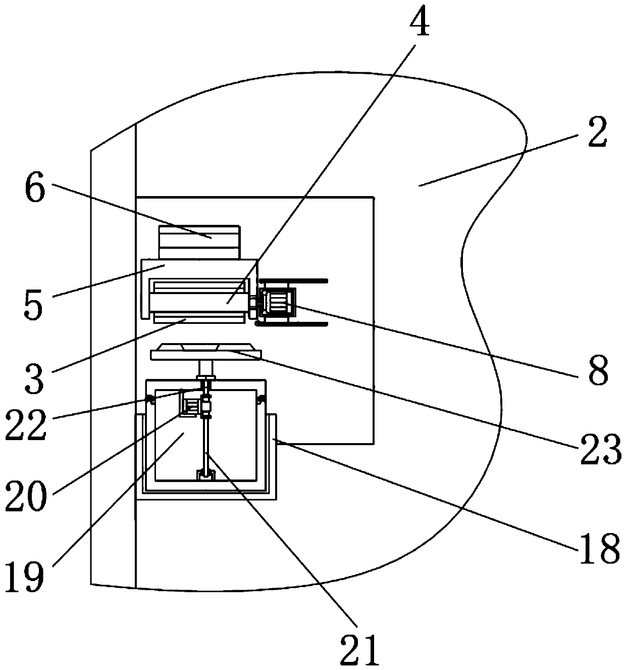
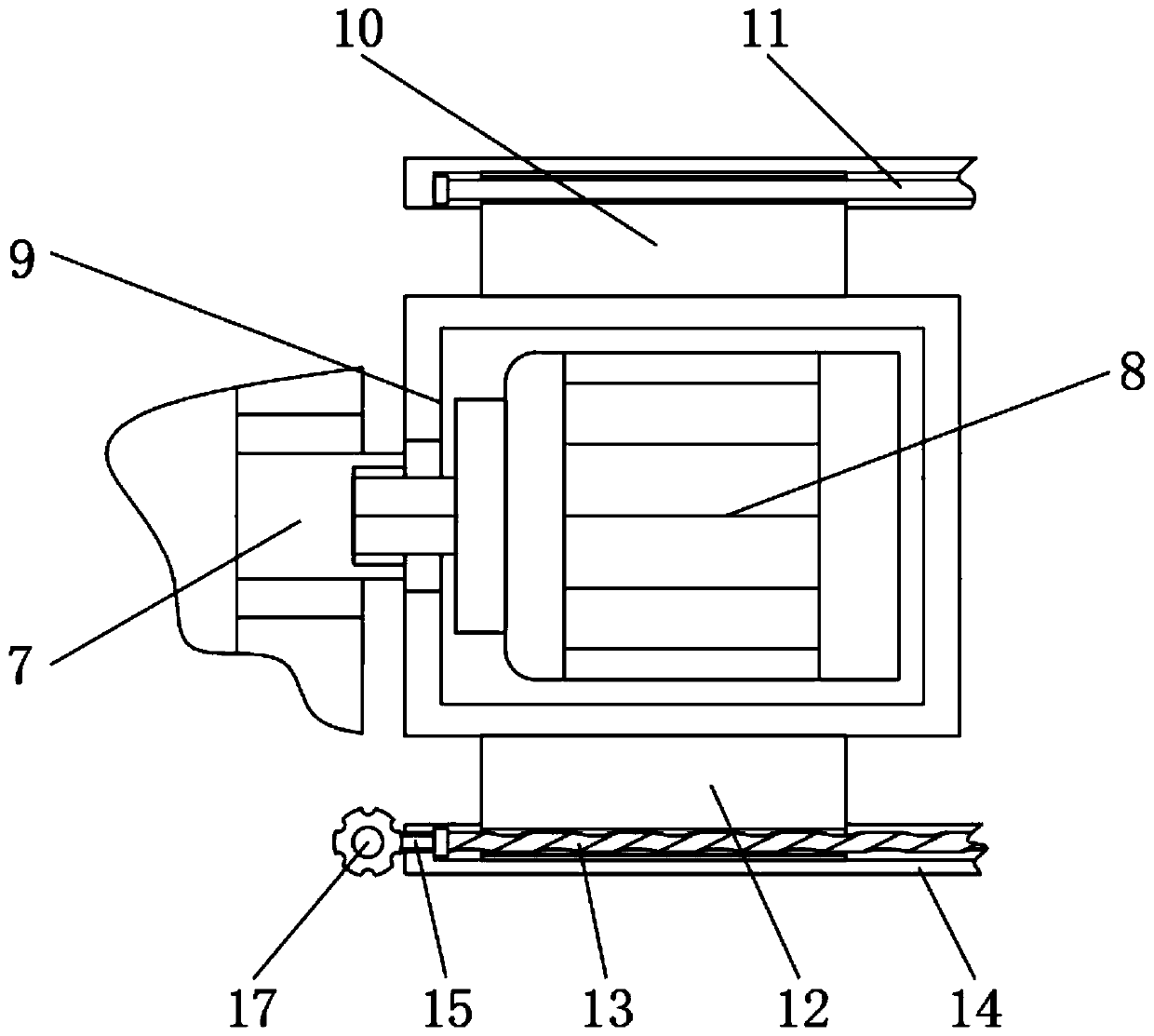
[0022] Embodiment one, by Figure 1-4 Given, the present invention comprises a cabinet body 1, a closed door 2 is installed on the surface of the cabinet body 1, a retaining pipe 3 is fixed on the surface of the closed door 2, and a movable rod 4 is installed in the inner chamber of the retaining pipe 3, and the movable rod 4 One end is equipped with support 5, and the top of support 5 is fixed with clamp block 6, and the other end of movable bar 4 is equipped with assembly bar 7, and one end of assembly bar 7 is equipped with motor 8, and the exterior of motor 8 is equipped with protective box 9, and protection The top of the box 9 is fixed with a first moving plate 10, the top of the first moving plate 10 is equipped with a sliding rod 11, the bottom of the protective box 9 is equipped with a second moving plate 12, and the bottom of the second moving plate 12 is screwed with an adjusting rod 13. A fixed rod block 14 is installed on the outside of the adjusting rod 13, and a...

Embodiment 2

[0023] Embodiment 2, on the basis of Embodiment 1, the surface of the closed door 2 is equipped with a dust-proof pad, and the shape of the closed door 2 is a square. Through the setting of the closed door 2, the dust-proof pad is used to prevent the oil from spraying. Sputtering occurs, causing the lubricating oil to contaminate the inside of the cabinet 1 .

Embodiment 3

[0024] Embodiment three, on the basis of embodiment one, one end of the shaping rod 25 is fixed with a threaded rod, and one end of the threaded rod on the shaping rod 25 is threadedly connected with the side of the cabinet body 1 inner cavity, and through the setting of the shaping rod 25, the It utilizes the threaded rod to facilitate the installation work of the shaping rod 25, and facilitates the replacement work after it is damaged.


PUM


Abstract

The invention relates to the technical field of low-voltage switch cabinets. The invention further discloses a locking structure for the low-voltage switch cabinet, and solves the problem that the locking structure of the low-voltage switchgear currently on the market is partially damaged, due to the inability to disassemble the relevant parts, the locking mechanism cannot be used normally, and the lubricating oil cannot be applied when the low-voltage switchgear is in a closed state. The locking structure comprises a cabinet body, a sealing door is mounted on the surface of the cabinet body,a retention pipe is fixed to the surface of the sealing door, a movable rod is installed in an inner cavity of the retention pipe, a support is installed at one end of the movable rod, a clamping block is fixed to the top of the support, an assembling rod is installed at the other end of the movable rod, a motor is installed at one end of the assembling rod, a protection box is installed outside the motor, and a first movable plate is fixed to the top of the protection box. The locking structure has the advantages that after being locally damaged, the locking structure can be detached and replaced, the locking mechanism can be continuously used, and lubricating oil can be automatically sprayed when the locking structure is in a closed state.

Description

technical field [0001] The invention belongs to the technical field of low-voltage switch cabinets, in particular to a locking structure for low-voltage switch cabinets. Background technique [0002] Low-voltage switchgear is suitable for power plants, petroleum, chemical industry, metallurgy, textiles, high-rise buildings and other industries, as power transmission, power distribution and power conversion. [0003] However, the locking structure used for low-voltage switchgear on the market cannot be partially disassembled during use, so that after these parts are damaged, the overall locking mechanism is directly damaged and cannot be used normally; After a period of time, there will be a case of jamming. At this time, it is necessary to apply lubricating oil, but when the low-voltage switchgear is in a closed state, the lubricating oil cannot be manually applied. For this reason, a method for low-voltage switchgear is proposed. locking structure. Contents of the invent...

Claims


Application Information

Patent Timeline
IPC IPC(8): H02B1/30H02B1/32E05B15/00E05B17/00E05B17/08E05B47/00
CPCE05B15/0013E05B17/0004E05B17/08E05B47/0012H02B1/30H02B1/306H02B1/32
Inventor 龚斌
Owner 江苏海潮电气科技有限公司
Why Eureka
Try Eureka