A kind of distribution cabinet assembly equipment and its assembly process

A technology for assembling equipment and power distribution cabinets, which is applied in the substation/power distribution device shell, substation/switchgear cooling/ventilation, electrical components, etc., which can solve the problem of difficult positioning of power distribution cabinets and large volume of power distribution cabinets , bulky structure and other problems, to achieve the effect of improving firmness and reliability, easy splicing and installation, and firm and reliable installation

Active Publication Date: 2021-10-15
SUZHOU HUAYUAN ELECTRIC
View PDF13 Cites 1 Cited by
  • Summary
  • Abstract
  • Description
  • Claims
  • Application Information

AI Technical Summary

Problems solved by technology

[0007] Aiming at the problems in the prior art, the object of the present invention is to provide a power distribution cabinet assembly equipment and its assembly process to solve the problem that the power distribution cabinet is large in size and heavy in structure. During the installation process of the power distribution cabinet, two adjacent distribution cabinets The position of the electric cabinet is difficult to place accurately, which makes it difficult to fix the fixed connection of two adjacent power distribution cabinets

Method used


Image

  • A kind of distribution cabinet assembly equipment and its assembly process
  • A kind of distribution cabinet assembly equipment and its assembly process
  • A kind of distribution cabinet assembly equipment and its assembly process

Examples


Embodiment Construction

[0038] The embodiments of the present invention will be described in detail below with reference to the accompanying drawings, but the present invention can be implemented in many different ways defined and covered by the claims.

[0039] In order to make the technical means, creative features, goals and effects achieved by the present invention easy to understand, the present invention will be further described below in conjunction with specific illustrations.

[0040] It should be noted that when an element is said to be "fixed" to another element, it may be on the other element or there may be an intervening element. When an element is referred to as being "connected to" another element, it can be directly connected to the other element or intervening elements may also be present. The terms "vertical", "horizontal", "left", "right" and similar expressions are used herein for the purpose of illustration only and do not represent the only embodiment.

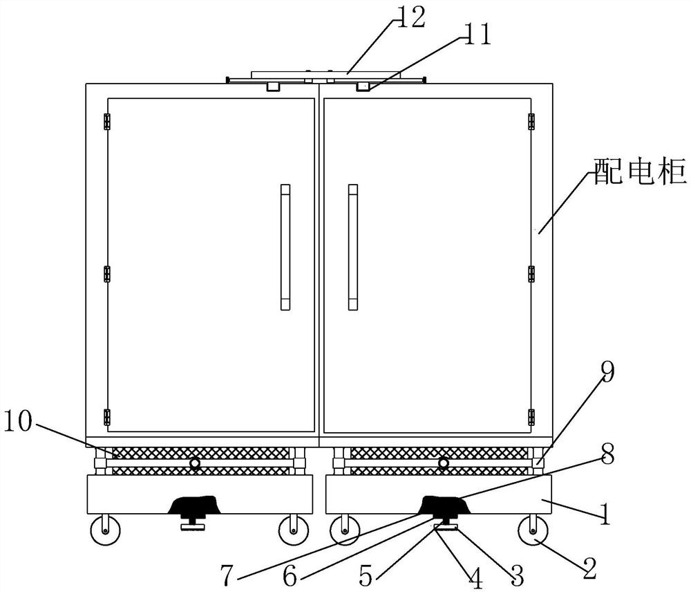
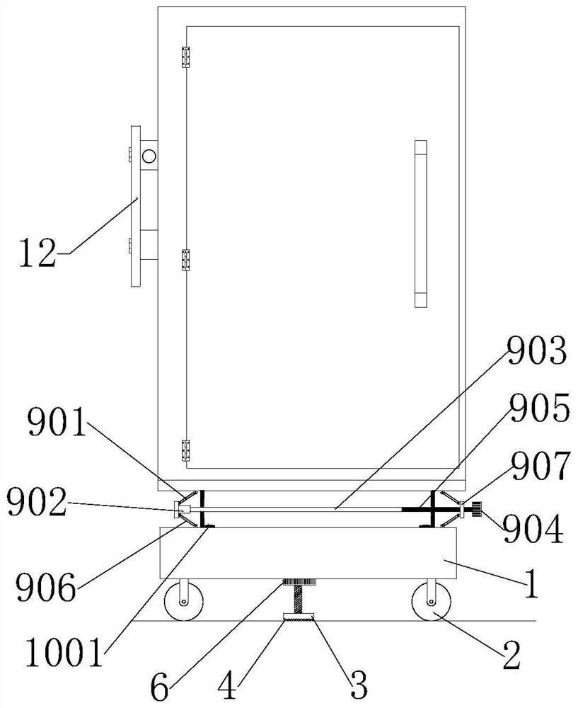
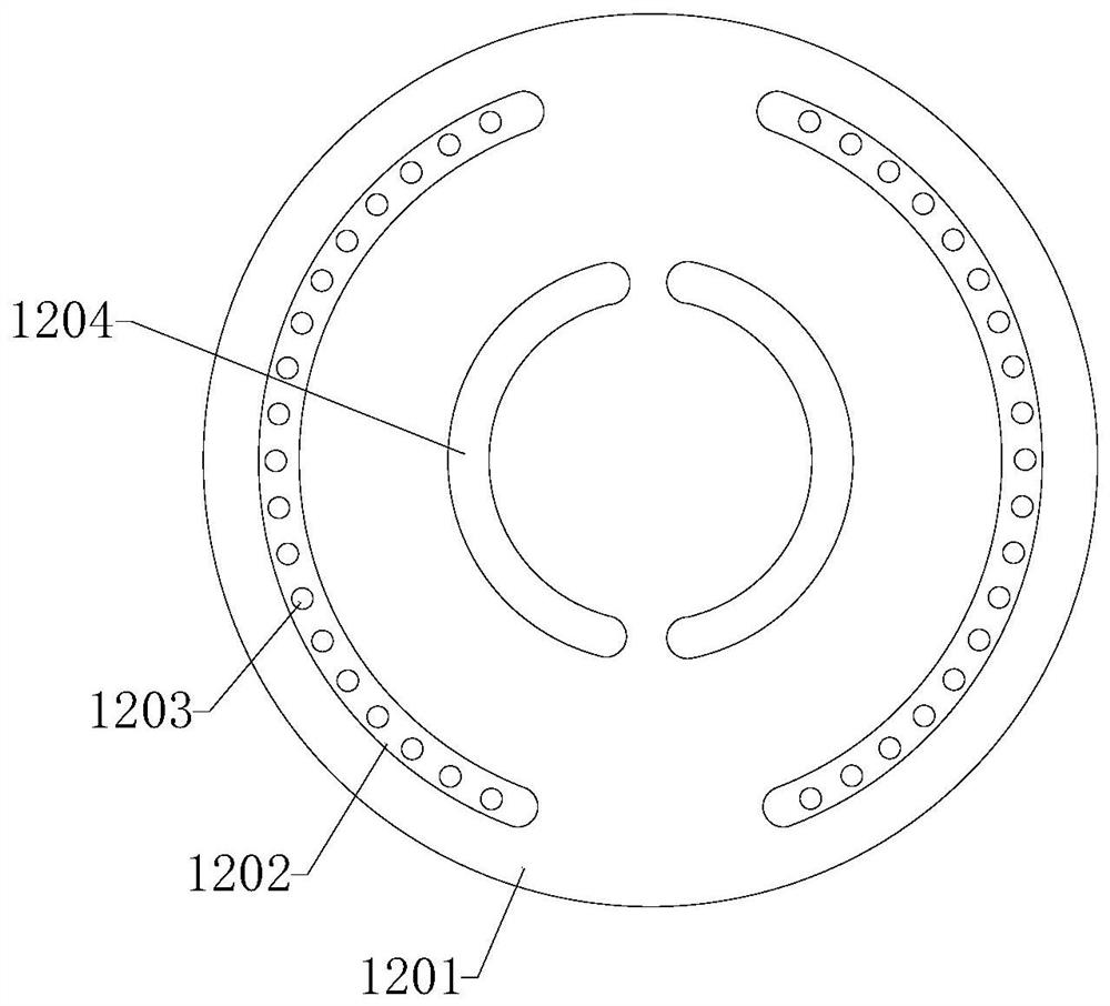
[0041] see Figure 1-...


PUM


Abstract

The invention discloses a power distribution cabinet assembly equipment and its assembly process, and relates to the technical field of electric appliance construction. The power distribution cabinet assembly equipment includes a bottom support plate arranged at the bottom of the power distribution cabinet, and a clamping plate installed at the top of the power distribution cabinet. device, a lifting assembly is provided between the top of the bottom support plate and the power distribution cabinet, walking wheels are provided at the corners of the bottom end of the bottom support plate, and the front and rear sides of the bottom support plate are symmetrically provided with A circular hole-shaped nut clamping groove, a circular hole-shaped first relief hole is opened at the center of the top circle of the nut clamping groove. In the present invention, a plugging net is installed on the top of the bottom support plate, and the plugging net is fixed on the bottom of the power distribution cabinet. The top of the plugging net is fixed along the bottom edge of the power distribution cabinet by screws, so that The air outlet at the bottom of the power distribution cabinet is blocked by the sealing net to prevent insects from crawling into the power distribution cabinet through the air outlet when the power distribution cabinet is installed outdoors.

Description

technical field [0001] The invention relates to the technical field of electrical appliance construction, in particular to a power distribution cabinet assembly equipment and an assembly process thereof. Background technique [0002] Power distribution cabinets (boxes) are divided into power distribution cabinets (boxes), lighting distribution cabinets (boxes), and metering cabinets (boxes), which are the final equipment of the power distribution system. The power distribution cabinet is a general term for the motor control center. The power distribution cabinet is used in the occasions where the load is relatively scattered and there are few circuits; the motor control center is used in the occasions where the load is concentrated and there are many circuits. They distribute the electric energy of a certain circuit of the upper-level power distribution equipment to the nearest load. This level of equipment shall provide protection, monitoring and control of the load. [...

Claims


Application Information

Patent Timeline
Patent Type & Authority Patents(China)
IPC IPC(8): H02B3/00H02B1/56H02B1/52H02B1/30H02B1/28
CPCH02B1/28H02B1/308H02B1/52H02B1/565H02B3/00
Inventor 张庆宇其他发明人请求不公开姓名
Owner SUZHOU HUAYUAN ELECTRIC
Why Eureka
Try Eureka