

Psychological strain capacity testing device
A technology of adaptability and testing device, applied in the field of psychology education, can solve the problems of inconvenient portability and huge structure of the testing device.
- Summary
- Abstract
- Description
- Claims
- Application Information
AI Technical Summary
Problems solved by technology
Method used
Image

Examples
Embodiment 1
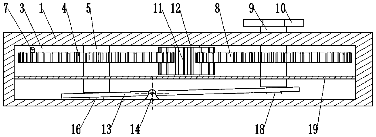
[0036] as attached Figure 1-Figure 3 Shown: Psychological strain capacity testing device, including table board 1, on the table board 1 sliding is provided with several output buttons 2, and the peripheral wall of output button 2 is glued and fixed with sponge (or rubber), and output button 2 The upper end is exposed from the desktop. Specifically, the table board 1 is provided with an output hole for the output button 2 to pass through. The sponge on the output button 2 contacts the inner peripheral wall of the output hole and forms frictional resistance. The upper end of the output button 2 is glued and fixed with a buffer layer, and rubber is used as an example here.
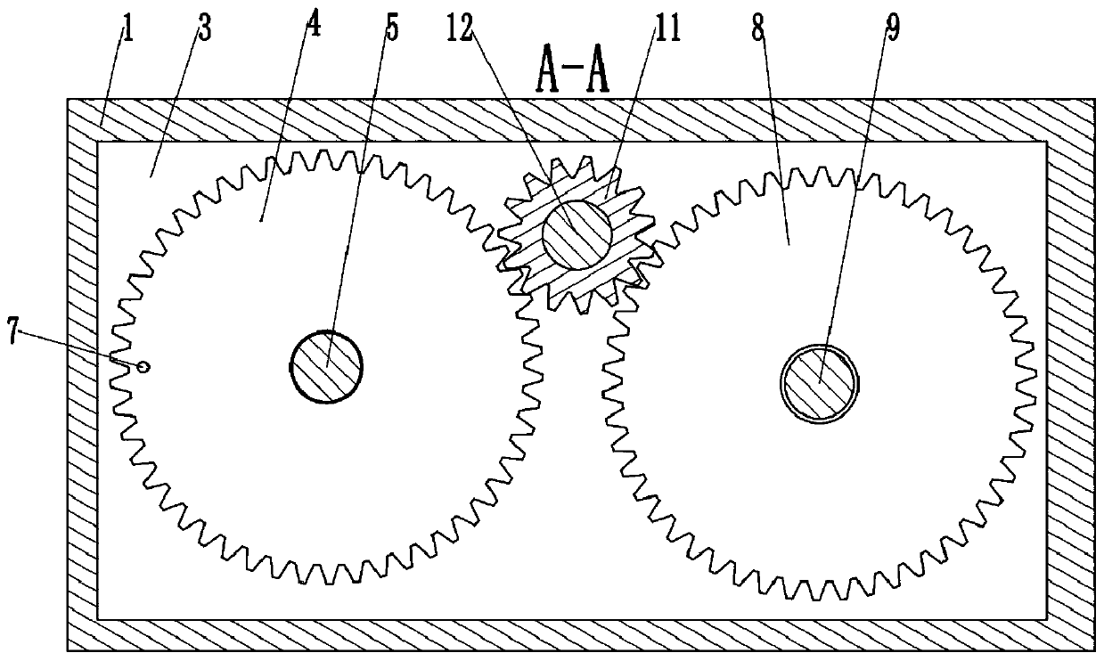
[0037] Such as figure 2 As shown, the table top 1 is provided with an accommodation chamber 3, and an output mechanism for pushing out the output button 2 is arranged in the accommodation chamber 3. The output mechanism includes a driven gear 4 and a driven shaft 5, and the top of the accommodation chamber...
Embodiment 2
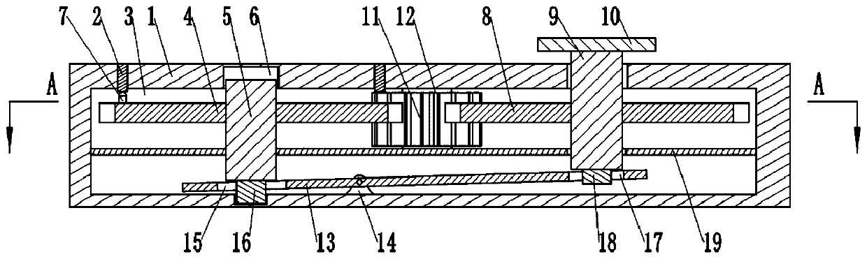
[0048] Such as Figure 4 , Figure 5 As shown, the difference between this embodiment and Embodiment 1 is that the middle part of the outer peripheral wall of the output button 2 is glued and fixed with a limiting protrusion 20, and the inner peripheral wall of the output hole is provided with a limiting groove for the movement of the limiting protrusion 20 21, where the limiting groove 21 is an annular groove. A sleeve 22 is arranged on the boss 7 to slide axially, and a spherical contact 23 is fixed on the top of the sleeve 22 by glueing; 24 is a compression spring, and the upper end of the second elastic reset member 24 is inserted into the sleeve 22 and fixed by welding with the contact 23. Under normal conditions, the second elastic return member 24 makes the top of the contact 23 be inserted into the output hole.
[0049] The basic principle of this embodiment is the same as that of Embodiment 1, but when the operator rotates the control member 10 to drive the equipmen...
PUM
 Abstract
Description
Claims
Application Information