Novel test tube rack device for clinical laboratory

A technology for clinical testing and test tube racks, applied in the direction of test tube racks/clamps, laboratory appliances, etc., can solve the problems of unfavorable clinical laboratory tests, poor fixation effect, poor applicability, etc., to improve safety, facilitate transportation, and facilitate cleaning effect

Inactive Publication Date: 2020-08-04
边静
View PDF0 Cites 7 Cited by
  • Summary
  • Abstract
  • Description
  • Claims
  • Application Information

AI Technical Summary

Problems solved by technology

[0002] The Laboratory Department is a bridge between clinical medicine and basic medicine, including clinical chemistry, clinical microbiology, clinical immunology, hematology, and blood transfusion. The samples are stored, and the test tubes need to be placed on the test tube racks to facilitate the storage of the inspectors. The traditionally used test tube racks are generally wooden racks or bamboo racks. Because there is a large gap between the test tubes in the test tube hole and the inner wall of the hole, the fixing effect is poor, and it is easy to collide during the process of moving the test tube rack, resulting in broken test tubes, which is not conducive to the inspection of the clinical laboratory.

Method used


Image

  • Novel test tube rack device for clinical laboratory
  • Novel test tube rack device for clinical laboratory
  • Novel test tube rack device for clinical laboratory

Examples


Embodiment Construction

[0026] The technical solutions in the embodiments of the present invention will be clearly and completely described below in conjunction with the accompanying drawings in the embodiments of the present invention. Obviously, the described embodiments are only a part of the embodiments of the present invention, rather than all the embodiments. Based on the embodiments of the present invention, all other embodiments obtained by those of ordinary skill in the art without creative work shall fall within the protection scope of the present invention.

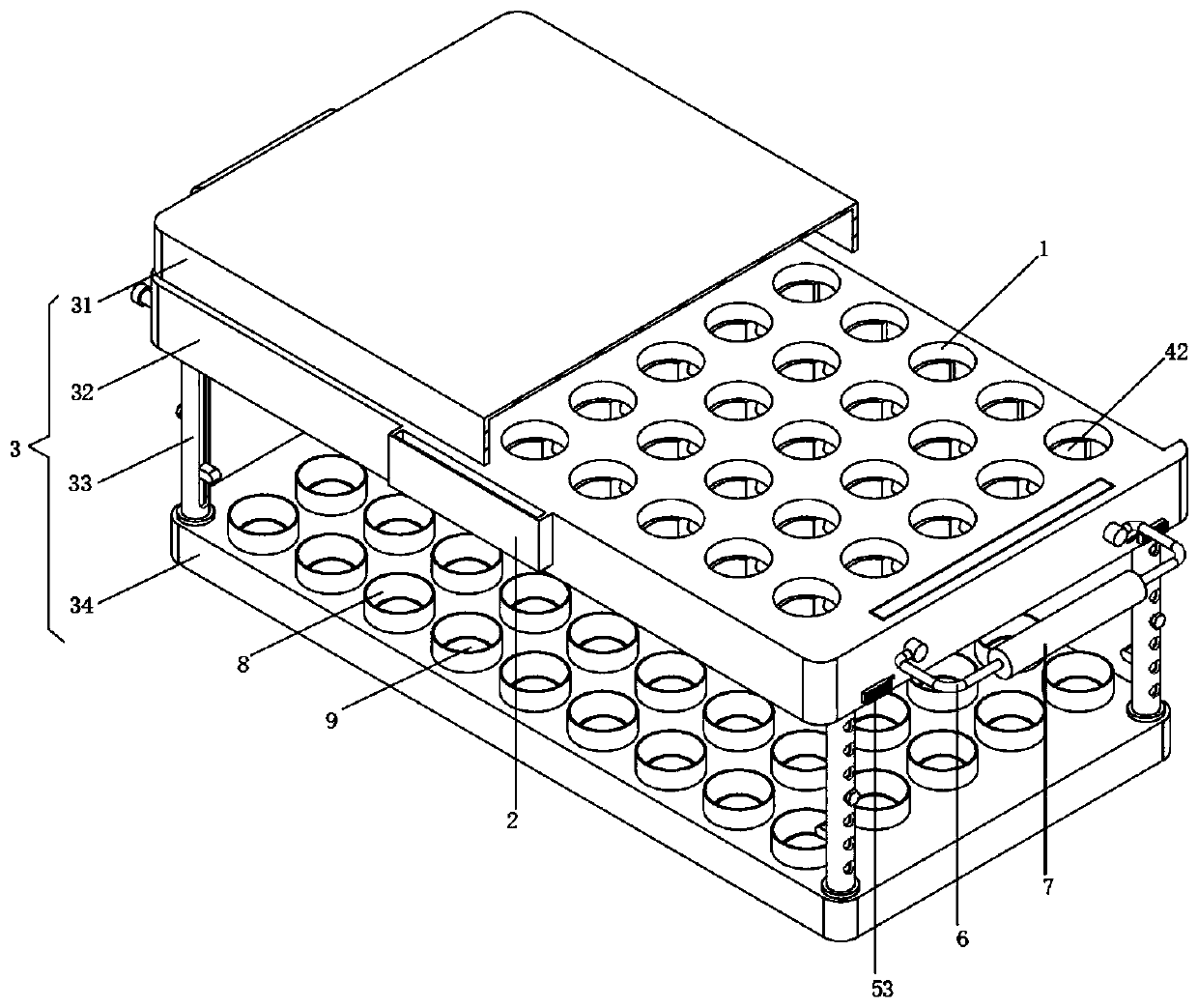
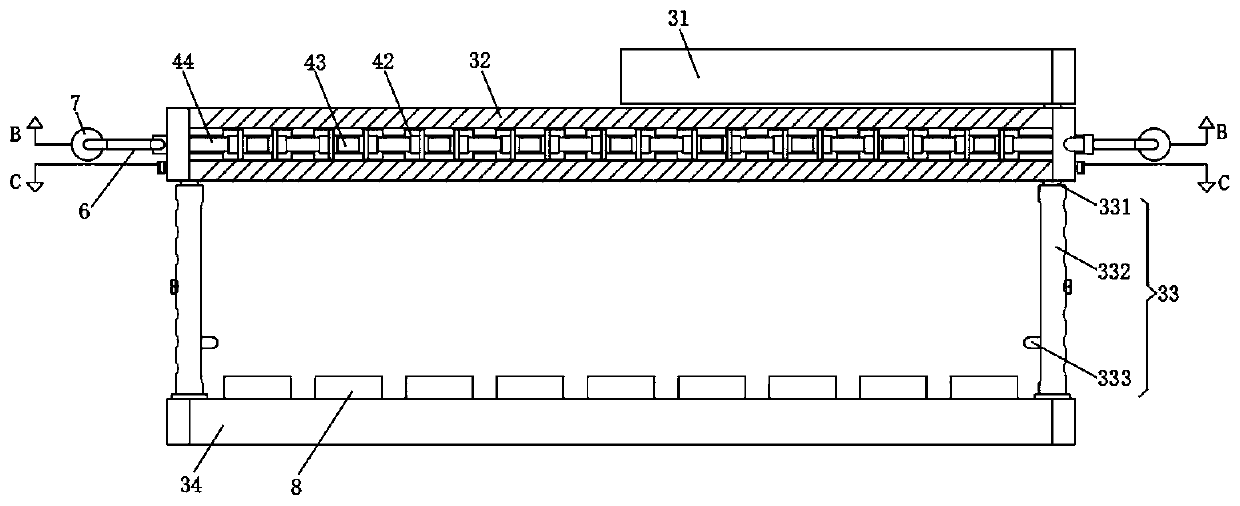
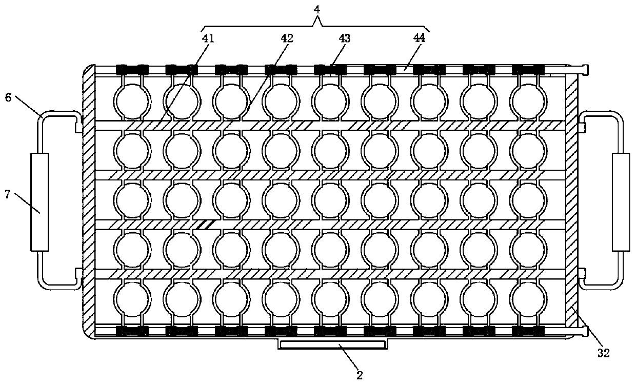
[0027] See Figure 1-5 , The present invention provides a technical solution: a new type of test tube rack device for clinical laboratory departments, including a test tube rack body 3, a fixing unit 5 and a clamping unit 4;

[0028] Test tube rack body 3: The test tube rack body 3 includes a top layer placement plate 32, a telescopic column 33 and a bottom plate 34. The top layer placement plate 32, the top cover 31 and the bottom plate 3...


PUM


Abstract

The invention discloses a novel test tube rack device for a clinical laboratory. The novel test tube rack device comprises a test tube rack body, fixing units and clamping units, wherein the test tuberack body comprises a top-layer placing plate, four sets of telescopic columns and a bottom plate, the telescopic columns are distributed at the top end of the bottom plate in an array mode, the topends of the telescopic columns are connected with the top-layer placing plate through the fixing units, test tube placing holes are formed in the top-layer placing plate in an array mode, and bottom-end limiting cylinders corresponding to the test tube placing holes are arranged on the bottom plate, each clamping unit comprises a guide rod, a clamping plate, a bidirectional screw column and a rotating shaft, rectangular through holes are formed in the middle of the top layer placing plate, the guide rods are installed on the inner wall of the rectangular through holes in parallel, the clampingplates are formed by connecting arc-shaped plates, the clamping degree of the test tube rack to test tubes can be adjusted, the test tube rack is suitable for containing the test tubes with differentlengths and diameters, and the test tubes are not prone to being broken due to collision with the test tube rack.

Description

Technical field [0001] The invention relates to the technical field of medical equipment, in particular to a new type of test tube rack device for clinical laboratory departments. Background technique [0002] Laboratory medicine is the bridge between clinical medicine and basic medicine, including clinical chemistry, clinical microbiology, clinical immunology, hematology, blood transfusion and other branches. In the inspection process, test tubes are often used, and the collected Samples are stored, while test tubes need to be placed on test tube racks for easy storage by inspectors. Traditionally used test tube racks are generally wooden racks or bamboo racks. These racks have a constant size of test tube placement holes and poor applicability. Because there is a large gap between the test tube in the test tube hole and the inner wall of the hole, the fixing effect is poor, and collisions are likely to occur during the process of moving the test tube rack, causing the test tube...

Claims


Application Information

Patent Timeline
Patent Type & Authority Applications(China)
IPC IPC(8): B01L9/06
CPCB01L9/06B01L2200/023B01L2200/18
Inventor 边静
Owner 边静
Why Eureka
Try Eureka